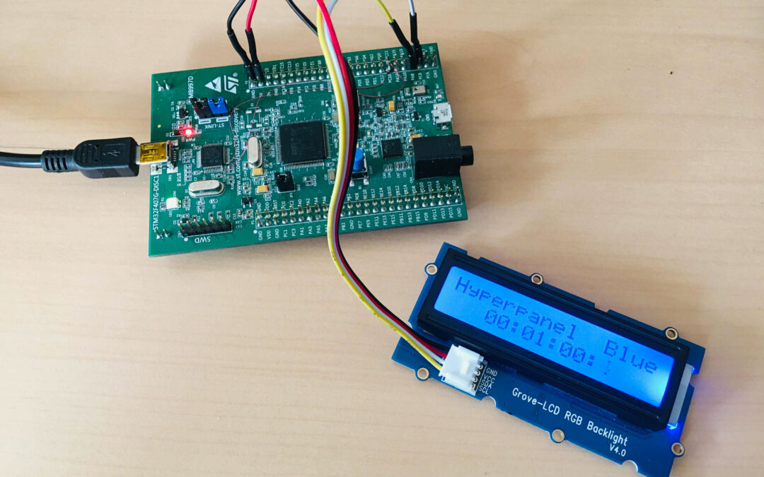
This tutorial gives an example of using a I2C screen device, with LCD display and RGB color background.
- A STMicroelectronics discovery kit with STM32F407VG MCU, order code STM32F407-DISC1 (replaces STM32F4DISCOVERY).
- USB 2.0 male to micro B cable (supplied with evaluation kit).
- A full installation of an Hyperpanel OS release on a linux based PC including tools for flashing and debugging. This tutorial requires release V10.03.02 for MB997D or higher. Hyperpanel OS releases are available for free in the Download section of the website.
- A Lunix PC with ARM gcc compiler, ARM gdb debugger and minicom installed.
- A text editor to edit or modify source codes (We are using vi in our demo).
- A Grove-LCD RGB Backlight V4.0 device from seeedstudio.
Hyperpanel OS V10.03.02 for MB997D (hypv100302.zip) or higher, available in the Download section.
Binary file
Hardware rework
The evaluation kit uses a USB port for power and debugger access. This connector is managed by a ST-LINK part, controlled by a STM32F103CBT6 (U2 on the board). The ST-LINK supports a virtual COM port on U2 pin 12 (ST-LINK_TX) and U2 pin 13 (ST-LINK_RX) but these pins are not connected to the USART of the STM32F407. To access to serial port for traces and messages, the solution is to use two flying wires to connect ST-LINK virtual COM port to the ASY1 HyperPanelOS serial port (see image):
U2 (STM32F103CBT6)                          P2 (CONNECTOR)
PIN 12 (ST-LINK_TX) <---------------------> PC11 (ASY1_RX)
PIN 13 (ST-LINK_RX) <---------------------> PC10 (ASY1_TX)
1. On www.tutorial.hyperpanel.com, select Download from the main menu.
2. Download “Hyperpanel OS V10.03.02 for MB997D” or higher release for the MB997D kit.
3. On your PC Linux, copy and unzip the zip file in your root directory, for example:
cp hypv100302.zip /home/hyperpanel
cd /home/hyperpanel
unzip hypv100302.zip
4. With a text editor, update hhome environment variable in the stm32m4 file:
cd ~/hypv100302/shells
vi stm32m4
Update the first line, according to your root directory:
export hhome=/home/hyperpanel/hypv100302
5. Save this file and an execute the command:
source stm32m4
6. From this tutorial, use the button “Binary file” to download the zip file containing the binary. Unzip this file:
unzip hpos-tuto315-bin.zip
7. Copy this binary file in HyperPanelOS release:
cp lcd_rgb.bin ~/hypv100302/boards/stm32m4/exe
8. Connect the LED bargraph to the MB997D.
LED-BARGRAPH    MB997D   SIGNAL   WIRE

VCC <---------> 3V       Power     Red
GND <---------> GND      Ground    Black
SDA <---------> PC9      I2C_SDA   Green
SCL <---------> PA8      I2C_SCL   Yellow
9. Connect the MB997D board to a USB port on your Linux PC using the USB cable supplied with the board. Wait for a window to appear, then close it.
10. Open a Terminal window and run minicom to get access to the Hyperpanel OS serial port and to the application messages:
minicom -D /dev/ttyACM0 -b 115200
11. Open another Terminal window on your computer and enter the following commands:
cd ~/hypv100302/shells
source stm32m4
exe
12. Upload software to the board:
hgdb
romload stm32m4 lcd_rgb
You should see messages similar to these:
Open On-Chip Debugger 0.10.0+dev-00001-g0ecee83-dirty (2017-02-10-06:53)
Licensed under GNU GPL v2
For bug reports, read
    http://openocd.org/doc/doxygen/bugs.html
0x00002ed6 in ?? ()
target halted due to debug-request, current mode: Thread
xPSR: 0x01000000 pc: 0x0000314c msp: 0x10002000
auto erase enabled
target halted due to breakpoint, current mode: Thread
xPSR: 0x61000000 pc: 0x20000046 msp: 0x10002000
wrote 393216 bytes from file lcd_rgb.bin in 11.143908s (34.458 KiB/s)
lcd_rgb.elf: No such file or directory.
Wait until the flashing operation is complete (approx. 30 seconds). The last message (lcd_rgb.elf: No such file or directory) is normal
13. You can now press on the reset button (black button) of the MB997D. Hyperpanel OS and the application will start. The screen displays some texts, the backlight color constantly changed from red, green, blue , white, etc. The application also send a clock counter on the serial port.
To go further
If you want to edit the source code, write modifications, compile, link, etc., here’s how to do it :
- From this tutorial, use the button “Source code” to download the zip file containing the source file. Unzip this file:
unzip hpos-tuto315-source.zip
- Copy this source code in HyperPanelOS release:
cp lcd_rgb.c ~/hypv100302/user/stm32app
- Copy the link file in Hyperpanel release:
cp lcd_rgb.lst ~/hypv100302/boards/stm32m4/exe
- You can edit and make any modifications you want in the source file.
cd ~/hypv100302/user/stm32app
vi lcd_rgb.c
- Save the source file.
- Compile the source file:
cd ~/hypv100302/user/stm32app
cmm lcd_rgb
- Call the linker to create the new binary file:
exe
lhypos lcd_rgb
- You can now upload this new binary to the board, in the same way as in the previous Installation chapter.
- The app gives an “how to use” example of an I2C device in “write” mode. The I2C driver available with HyperPanel OS support several controller/buses in parallel. In the case of the MB997D, ther is only one bus.
- The Grove-LCD RGB Backlight component include 2 different I2C devices: One is the LCD display, the other one is the RGB colored background.
- The I2C driver support IO lists, including waits, conditionnal jumps and intricated loops. We use here some “waits” command for initialization sequence, according information of datasheets.
- The driver provides two software interfaces in order to allow ease of use and versatility: Blocking and non blocking interfaces. We use here the blocking interface (i2c_write()).
- Compared with other I2C devices featured in other tutorials, this RGB screen requires 5V rather than 3.3V power.
Documents
Links
Let’s try
hypos-tuto315-source
/*
**  lcd_rgb.c - Sample code for HyperpanelOS ==============================  **
**                                                                           **
**  This simple code is located into the application container, it is run    **
**  by the VMK sub-operating system. On the other hand, the I/O container    **
**  runs all the drivers that are VMIO finite state machines.                **
**                                                                           **
**  The goal of this small app is to use a LCD-RGB I2C screen device.        **
**                                                                           **
**  =======================================================================  **
*/


/* Documentation for I2C devices --------------------------------------------

   (1) HD44780.pdf Hitachi Dot Matric Liquit Crystal Display Controller/Driver
   (2) PCA9633.pdf NXP 4-bit Fm+I2C-Bus LED driver - Product data sheet

*/
/* Include files and external reference -------------------------------------*/

#include <hypos.h>                     // Hyperpanel OS basic interfaces.    */
#include <drv_asy.h>                   // Prototype of "asy_write()".        */
#include <drv_i2c.h>                   // Prototype of "i2c_*()".            */


/* Internal defines of this module ------------------------------------------*/

#define  TICK                 1000     // Code for tick event.

#define DUMMY_AD              0xFF     // I2C dev address - Dummy for wait.
#define LCD_AD                0x7c     // I2C dev address - LCD.
#define RGB_AD                0xc4     // I2C dev address - RGB.

#define RED                   0x04     // I2C register - RGB background color.
#define GREEN                 0x03     // I2C register - RGB background color.
#define BLUE                  0x02     // I2C register - RGB background color.

#define SCREEN_INIT              0     // I2C command - Screen initialisation
#define SET_LINE1                1     // I2C command - Cursor on line 1
#define SET_LINE2                2     // I2C command - Cursor on line 2


/*  Internal global variables of this module --------------------------------*/

    static unsigned int idto         ; // Timer identifier.


/* SCREEN_INIT command ......................................................*/

    static const char screen_init[]  = // I2C command - Screen initialisation
      {

/*    Length-1, Address, Control byte, Data byte                             */

      1, DUMMY_AD ,   50             , // I2C temporisation 50 ms

      2, LCD_AD   , 0x80 , 0x3C      , // LCD dev  : FUNCTION_SET try 1
                                       // Ctrl byte: 10000000 RS=0
                                       // Data byte: 00111100 2-line, on

      1, DUMMY_AD ,   40             , // I2C temporisation 40 ms

      2, LCD_AD   , 0x80 , 0x3C      , // LCD dev  : FUNCTION_SET try 2
                                       // Ctrl byte: 10000000 RS=0
                                       // Data byte: 00111100 2-line, on

      1, DUMMY_AD ,   40             , // I2C temporisation 40 ms

      2, LCD_AD   , 0x80 , 0x3C      , // LCD dev  : FUNCTION_SET try 3
                                       // Ctrl byte: 10000000 RS=0
                                       // Data byte: 00111100 2-line, on

      2, LCD_AD   , 0x80 , 0x0C      , // LCD dev  : DISPLAY_SWITCH
                                       // Ctrl byte: 10000000 RS=0
                                       // Data byte: 00001100 on,off,off

      1, DUMMY_AD ,    40            , // I2C temporisation more than 39us

      2, LCD_AD   , 0x80 , 0x01      , // LCD dev  : SCREEN_CLEAR
                                       // Ctrl byte: 10000000 RS=0
                                       // Data byte: 00000001 clear

      1, DUMMY_AD ,    2             , // I2C temporisation more than 1.53ms

      2, RGB_AD   , 0x00 , 0x00      , // RGB dev  : REG_MODE1, init
                                       // Register : 0x00
                                       // Data     : 0x00

      2, RGB_AD   , 0x08 , 0xFF      , // RGB dev  : REG_OUTPUT
                                       // Register : 0x08
                                       // Data     : 0xFF PWM & GRPPWM

      0, 0        , 0    , 0         , // End of command set
      }                              ; //

/* SET_LINE1 command ........................................................*/

    static const char set_line1[]    = // I2C command - Screen initialisation
      {

/*    Length-1, Address, Control byte, Data byte                             */

      2, LCD_AD   , 0x80 , 0x80      , // LCD dev  : CURSOR_RETURN
                                       // Ctrl byte: 10000000 RS=0
                                       // Data byte: 10000000 line 1, on

      0, 0        ,    0 ,    0      , // End of commands
      }                              ; //

/* SET_LINE2 command ........................................................*/

    static const char set_line2[]    = // I2C command - Screen initialisation
      {

/*    Length-1, Address, Control byte, Data byte                             */

      2, LCD_AD   , 0x80 , 0xC0      , // LCD dev  : CURSOR_RETURN
                                       // Ctrl byte: 10000000 RS=0
                                       // Data byte: 11000000 line 2, on

      0, 0        ,    0 ,    0      , // End of commands
      }                              ; //

    static char   *command[] =         // I2C commands table
      {                                //
        (char*)&screen_init[0]       , // I2C command - SCREEN_INIT
        (char*)&set_line1[0]         , // I2C command - SET_LINE1
        (char*)&set_line2[0]         , // I2C command - SET_LINE2
        (char*)0
      }                              ; //

    static const char *text[]        = // Messages on scree
      {
        "Hyperpanel   Red"           , // Message for "red" animation
        "Hyperpanel Green"           , // Message for "green" animation
        "Hyperpanel  Blue"           , // Message for "blue" animation
        "Hyperpanel White"           , // Message for "white" animation
      }                              ;


/*  Prototypes --------------------------------------------------------------*/

    static int  loop_app_task(void*) ; // Prototype
    static int  wait_evt(void)       ; // Prototype
    static void set_command(int)     ; // Prototype
    static void write_string(char*)  ; // Prototype
    static void set_color(int,int)   ; // Prototype


/*  Beginning of the code ---------------------------------------------------

    loop_app_tsk         Application entry point
    wait_evt             Wait for applicative events
    set_command          Write a command on the screen
    write_string         Write a character string on the screen
    set_color            Set a color level on the screen background
*/

/*  Procedure loop_app_tsk --------------------------------------------------

    Purpose : This is our task main loop.
*/

int loop_app_tsk (void *param)
  {
    int             ev = TICK        ; // Our event
    int             curtime = 0      ; // Current time
    char            mess[16]         ; // Message to be sent on ASY0
    char            col = -1         ; // Color
    short           lev = -4         ; // Level

/* Step 1 - Start a timer that will send an event every second ..............*/

    set_uto(CLOCK      ,               // Timer mode: clock
            100        ,               // Duration in milliseconds
            TICK , 0   ,               // Event code and reserve field
            &idto     );               // Timer identifier

/* Step 1 - LCD & RGB screen initialisation .................................*/

    asy_write(0,(unsigned char*)"Init ... ",9);

    set_command(SCREEN_INIT)         ; // LCD/RGB initialization sequence

    asy_write(0,(unsigned char*)"done\r\n",6);


/* Step 3 - Main loop .......................................................*/

    wait_ev :                          // Beginning of loop label

    if ( ev == TICK )                  // If the event is the tick event
      {                                //

        curtime ++                   ; // Time incrementation

/* Step 3.1 - Display timer on serial port and on screen ....................*/

        hsprintf(mess                , // Format de timer message.
          "   %02d:%02d:%02d:%01d"   , //
          ((curtime/10)/3600)%24     , // Hour.
          ((curtime/10)/  60)%60     , // Minutes.
           (curtime/10)      %60     , // Seconds.
            curtime%10              ); // Thenths.

        if (!(curtime%10))             // Each second, send a trace.
          {                            //
            asy_write(0              , // Write on ASY0
              (unsigned char*)mess   , // the "mess" message
              strlen(mess)          ); // Count of bytes to be sent
            asy_write(0              , // Write on ASY0
              (unsigned char*)"\r\n" , // the "mess" message
              2                     ); // Count of bytes to be sent
          }

        set_command(SET_LINE2)       ; // Cursor on line 2.
        write_string(mess)           ; // Write current time on screen.
        set_command(SET_LINE1)       ; // Cursor on line 1.

/* Step 3.2 - Background color animation ....................................*/

        lev=(lev+4)%128              ; // Brightness level
        if (!(lev)) col=(col+1)%4    ; // Red/Green/Blue/White selection

        write_string(                  // Display title text on the screen.
               (char*)text[(int)col]);

        switch (col)
          {
            case 0 :
              set_color(RED  , lev)  ; // Set RED level
              set_color(GREEN,   0)  ; // Set GREEN level
              set_color(BLUE ,   0)  ; // Set BLUE level
              break                  ;

            case 1 :
              set_color(RED  ,   0)  ; // Set RED level
              set_color(GREEN, lev)  ; // Set GREEN level
              set_color(BLUE ,   0)  ; // Set BLUE level
              break                  ;

            case 2 :
              set_color(RED  ,   0)  ; // Set RED level
              set_color(GREEN,   0)  ; // Set GREEN level
              set_color(BLUE , lev)  ; // Set BLUE level
              break                  ;

            case 3 :
              set_color(RED  , lev)  ; // Set RED level
              set_color(GREEN, lev)  ; // Set GREEN level
              set_color(BLUE , lev)  ; // Set BLUE level
              break                  ;
          }
      }

    ev = wait_evt()                  ; // Unschedule until an event is received
    goto wait_ev                     ; // Wait for the next event

    return  0                        ; // Return code of the procedure
  }


/*  Procedure wait_evt ------------------------------------------------------*/
/*
    Purpose : Unschedule until the next event is received, whatever it is.
*/

static int wait_evt (void)
  {
    unsigned int    waitlist[1][3]   ; // Parameter of "waitevt_task"

/*****************************************************************************
 * Step 1 : Build a list with one WAIT_CODEINT entry that will accept all    *
 * ------   the event codes ranging from 0 to 20000. Then call               *
 *          "waitevt_task", we will be unscheduled until the next event will *
 *          be received                                                      *
 *****************************************************************************/

    waitlist[0][0]  = WAIT_CODEINT   ; // All events with
    waitlist[0][1]  = 0              ; // a code between 0
    waitlist[0][2]  = 20000          ; // and 20000

    waitevt_task(waitlist ,            // Address of waiting list
                 1        ,            // Size of "waitlist[]"
                 0        ,            // maximum waiting time = no
                 0        )          ; // Do not purge previous events

/*****************************************************************************
 * Step 2 : Here we are scheduled again. The VMK has written into its        *
 * ------   global variable "task_evt" a copy of the event that has          *
 *          scheduled us again.                                              *
 *****************************************************************************/

    return task_evt.code             ; // Return event code
  }


/*  Procedure set_command ---------------------------------------------------*/
/*
    Purpose : Send a set of commands to I2C devices.
*/

static void set_command(int cmd)
  {
    i2c_write(
      0                           ,    // Controller number
     -1                           ,    // Target I2C write address
      (unsigned char*)command[cmd],    // Command
      0                          );    // List of option flags
  }


/*  Procedure write_string --------------------------------------------------*/
/*
    Purpose : write a character string on the screen.
*/

static void write_string(char *s)
  {
    int             of = 0           ; // Offset for I2C frame building
    unsigned char   buf[32]          ; // Message to be sent on I2C

    memset(buf  ,strlen(s)+1,1);of++ ; // Lenght -1 ot the message
    memset(buf+of, LCD_AD   ,1);of++ ; // write address 01111100
    memset(buf+of, 0x40     ,1);of++ ; // Control Byte 01000000 (RS=1)
    memcpy(buf+of,s,strlen(s) )      ; //
    of=of+strlen(s)                  ; //
    memset(buf+of,0,1)               ; // End of frame

    i2c_write(0,-1,buf,0)            ; // Send I2C commands.
  }


/*  Procedure set_color -----------------------------------------------------*/
/*
    Purpose : Set a color level on RGB background
*/

static void set_color(int color, int level)
  {
    int             of = 0           ; // Offset for I2C frame building
    unsigned char   buf[8]           ; // Message to be sent on I2C

    memset(buf   ,    2  , 1); of++  ; // Lenght -1 ot the message
    memset(buf+of, RGB_AD, 1); of++  ; // write address
    memset(buf+of, color , 1); of++  ; // REG_RED
    memset(buf+of, level , 1); of++  ; //
    memset(buf+of, 0,      1)        ; // End of frame

    i2c_write(0,-1,buf,0)            ; // Send I2C commands.
  }
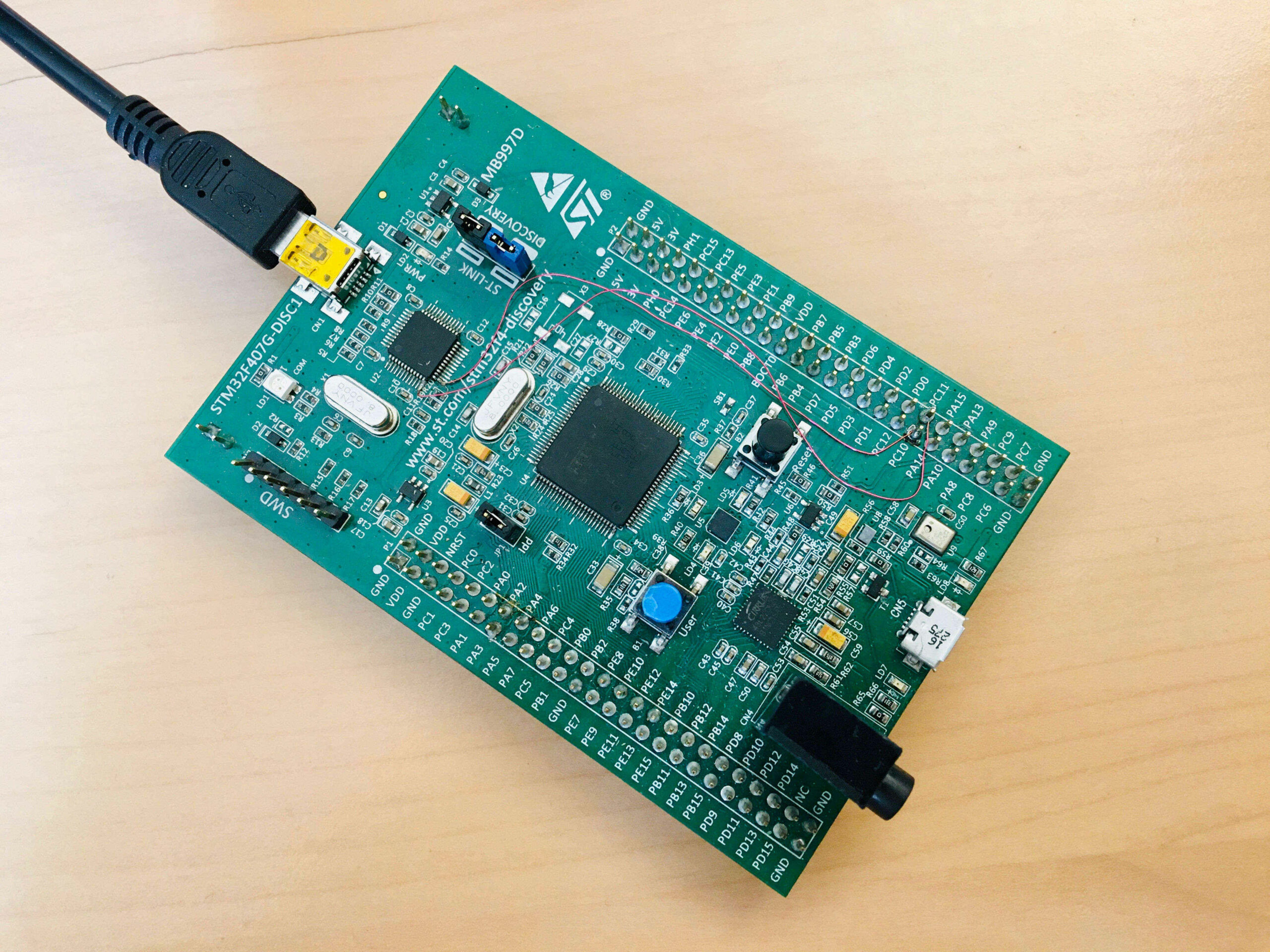
The STM32F407G-Disc1 / MB997D evaluation kit
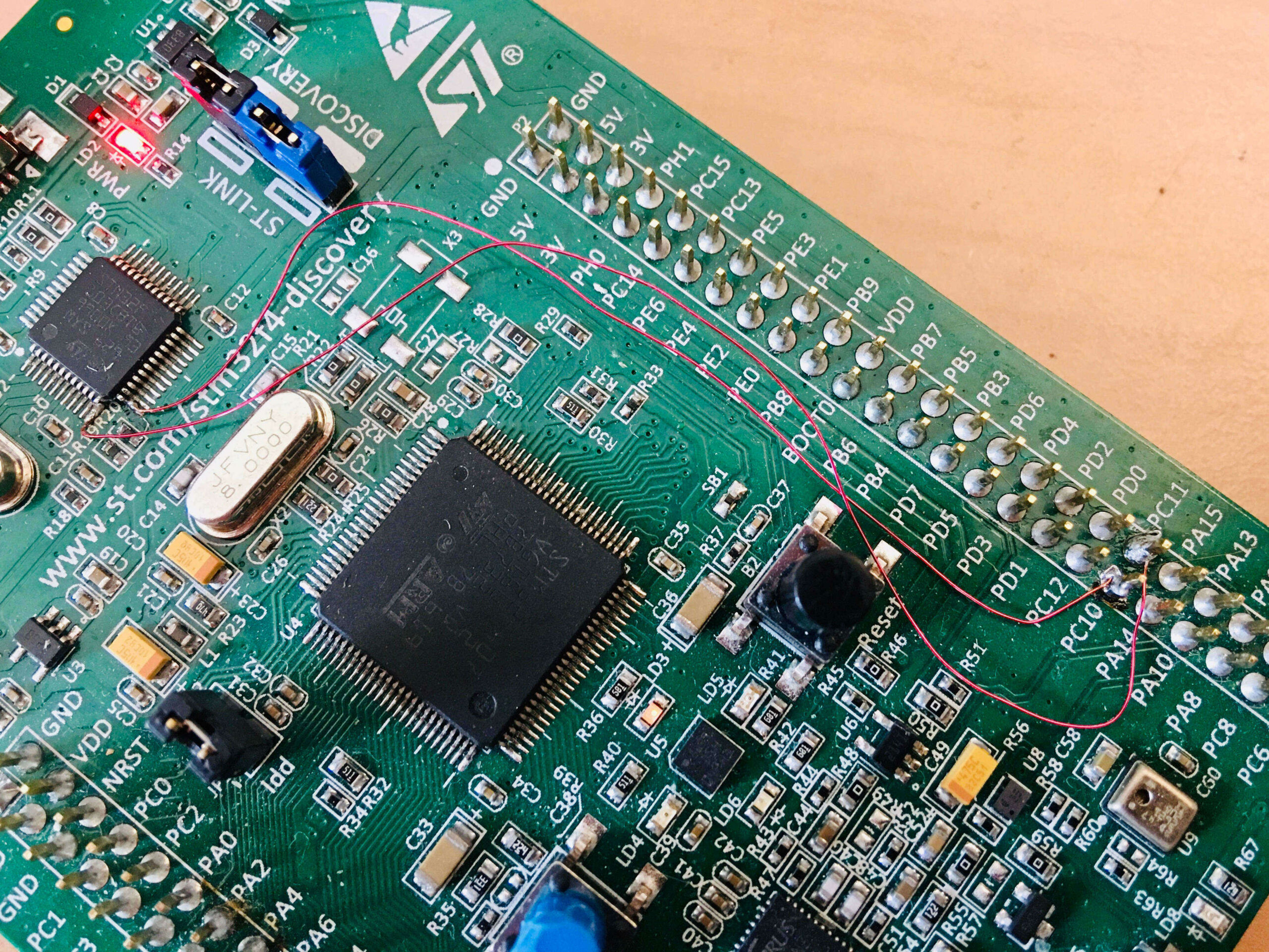
ST-LINK COM port connection to HyperPanelOS ASY1
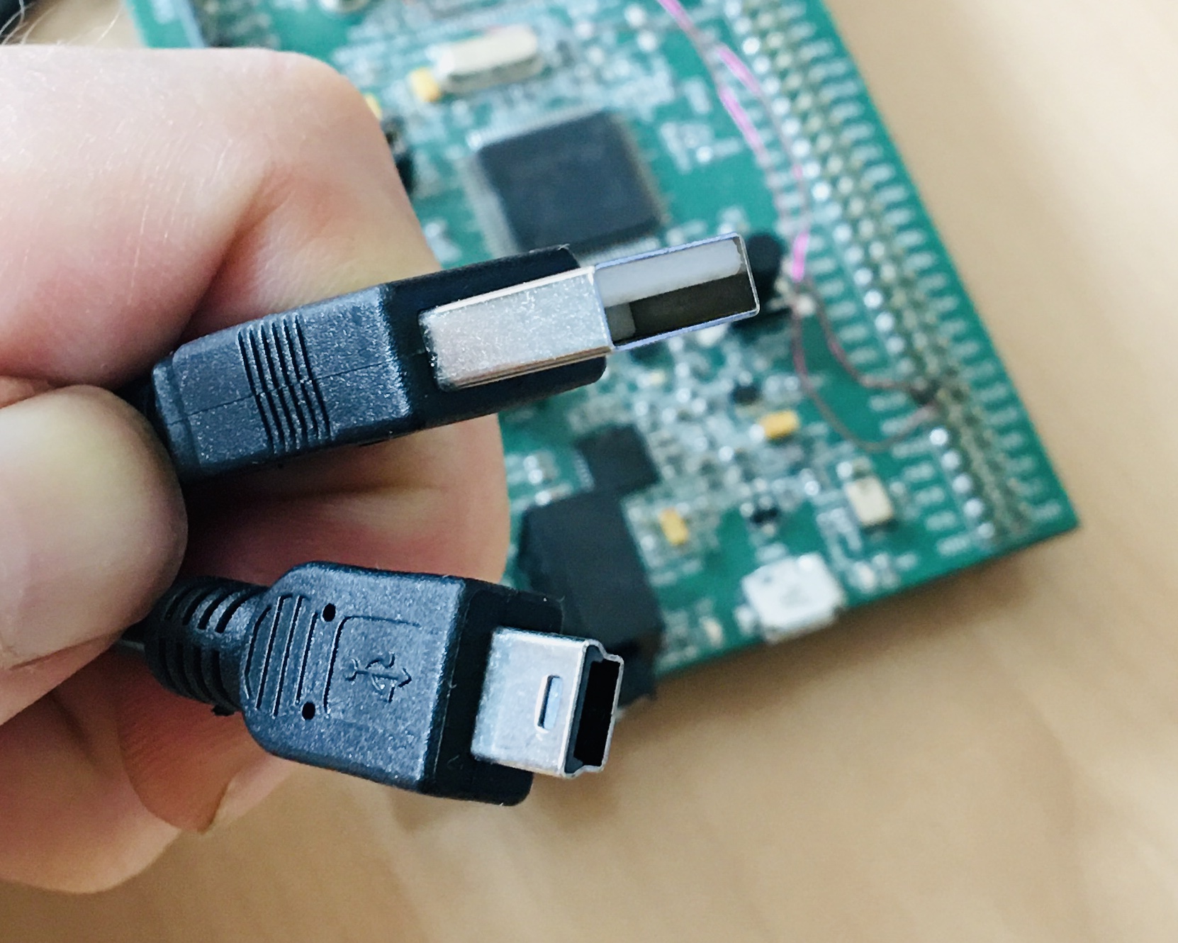
USB cable
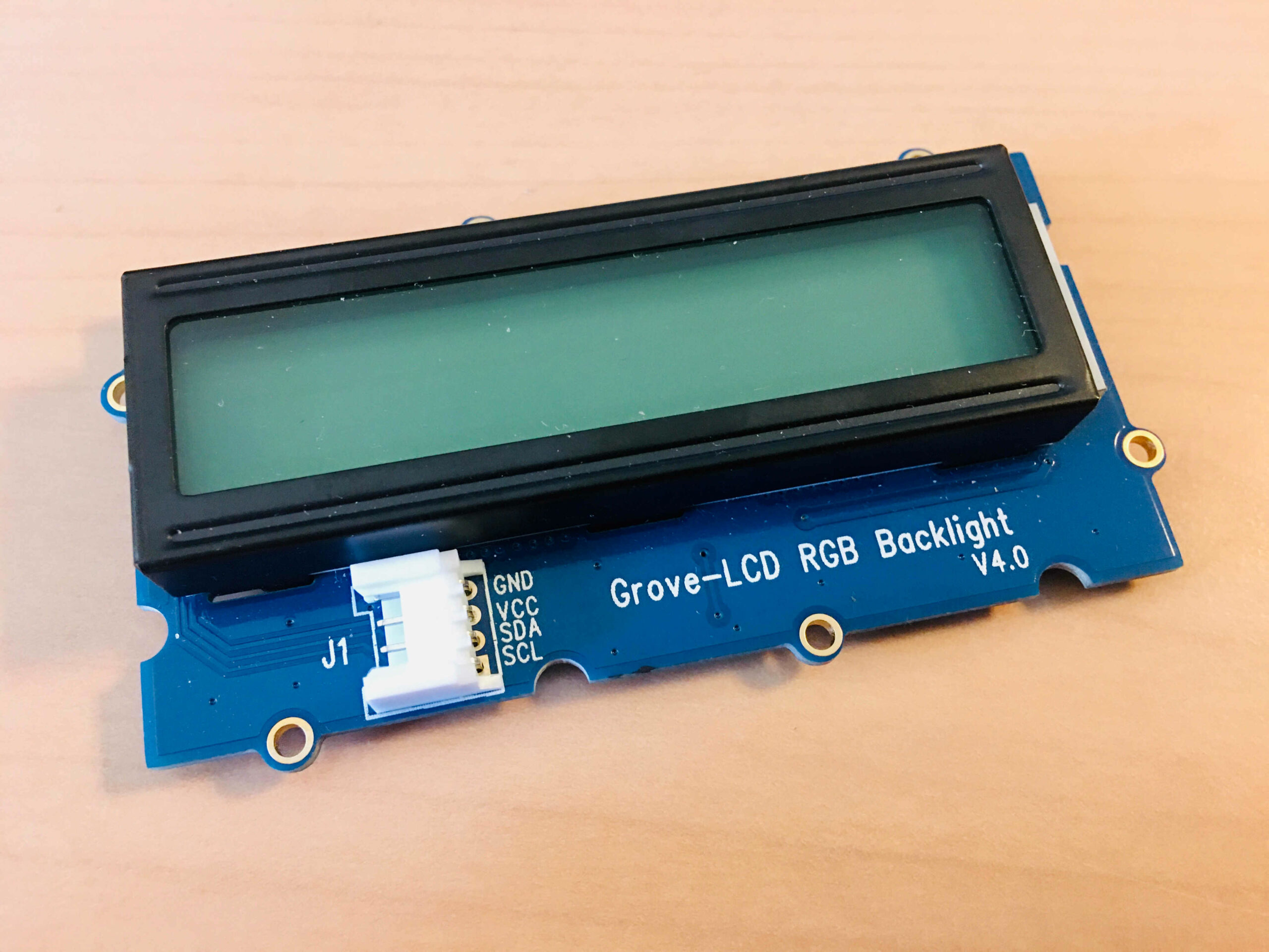
The Grove-LCD RGB Backligt V4.0
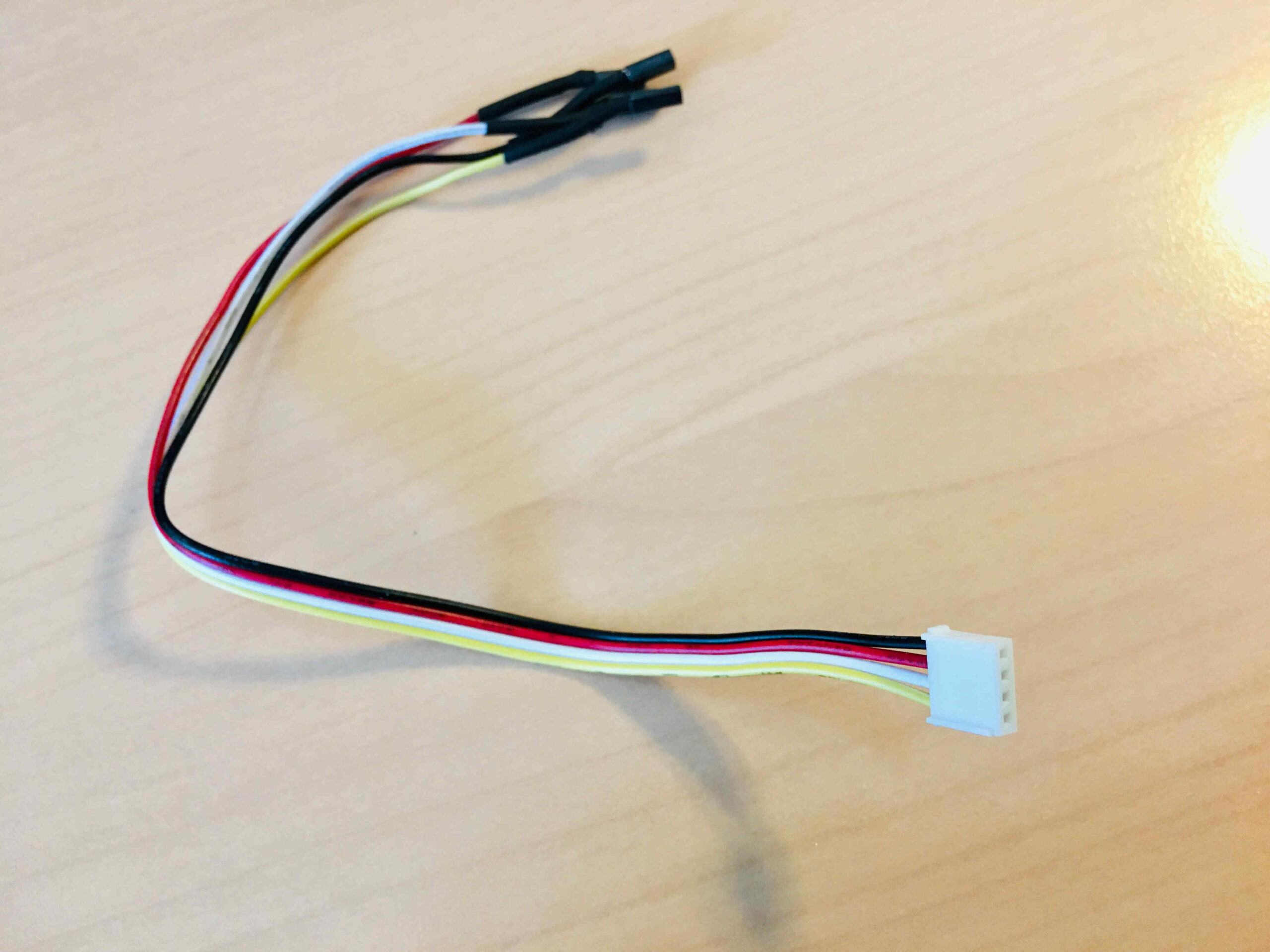
Wires for connections
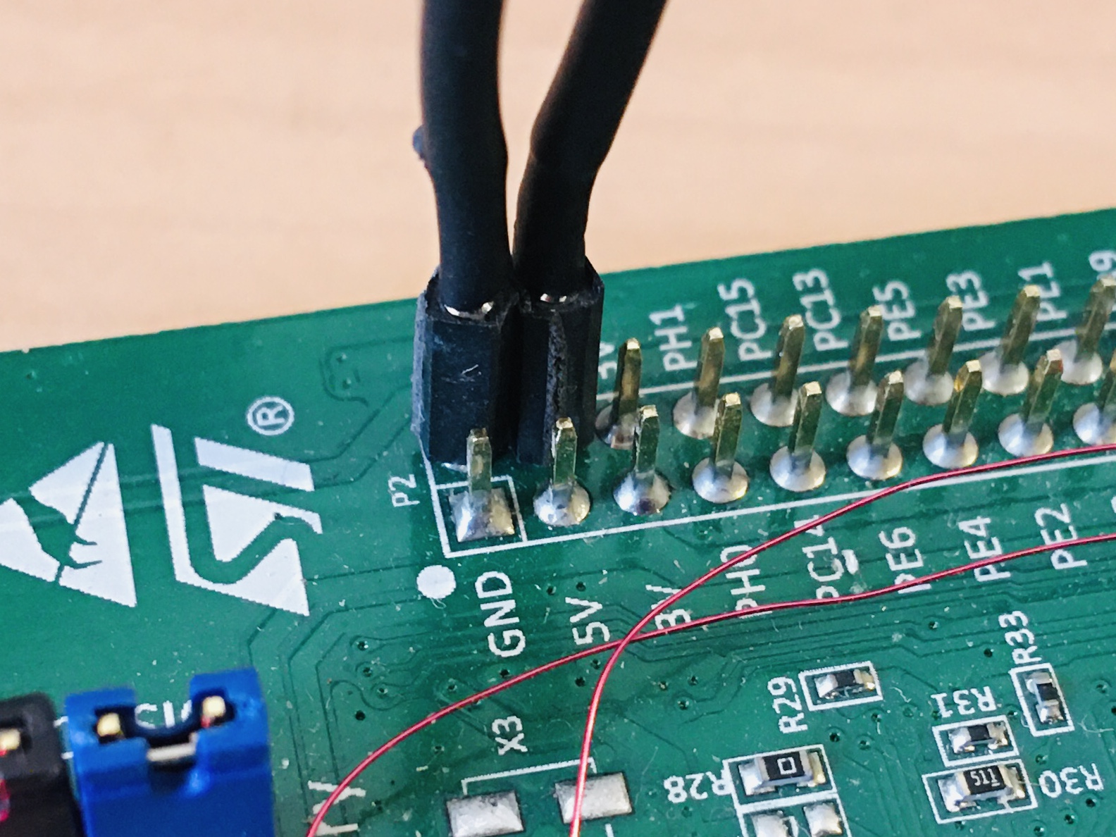
How to connect the power of the screen to the MB997D
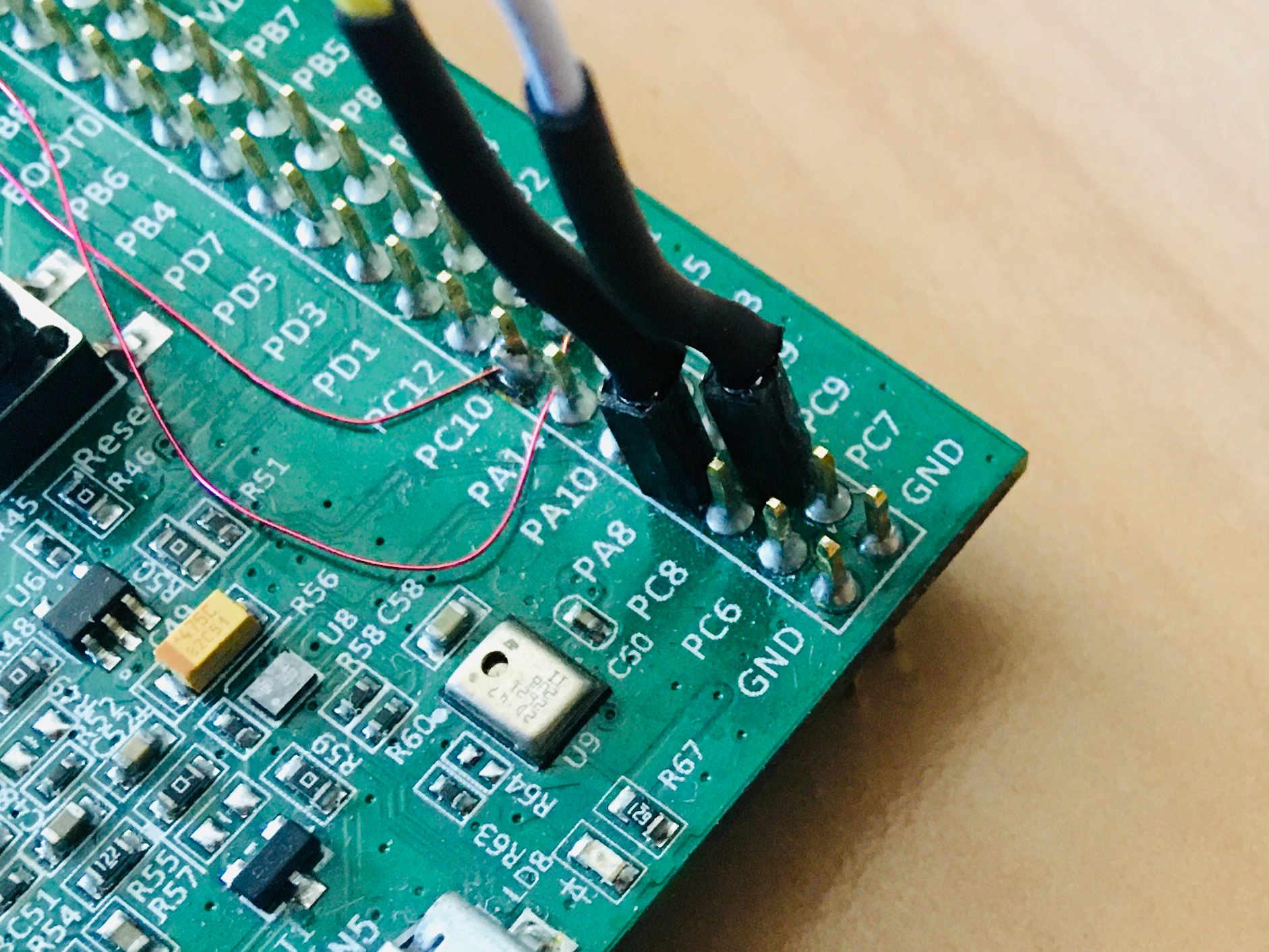
How to connect I2C signals of the screen to the MB997D
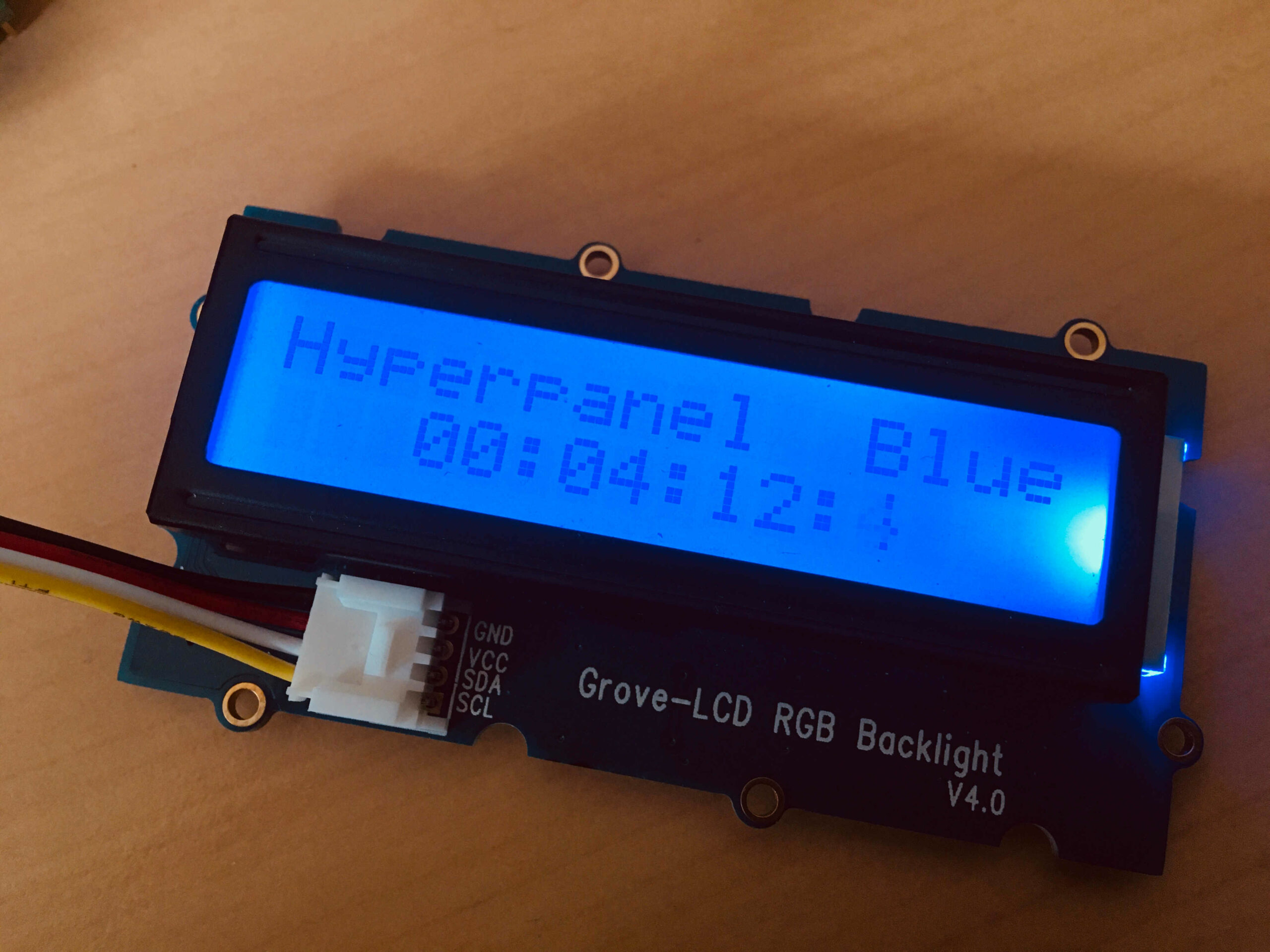
Application running – Blue screen
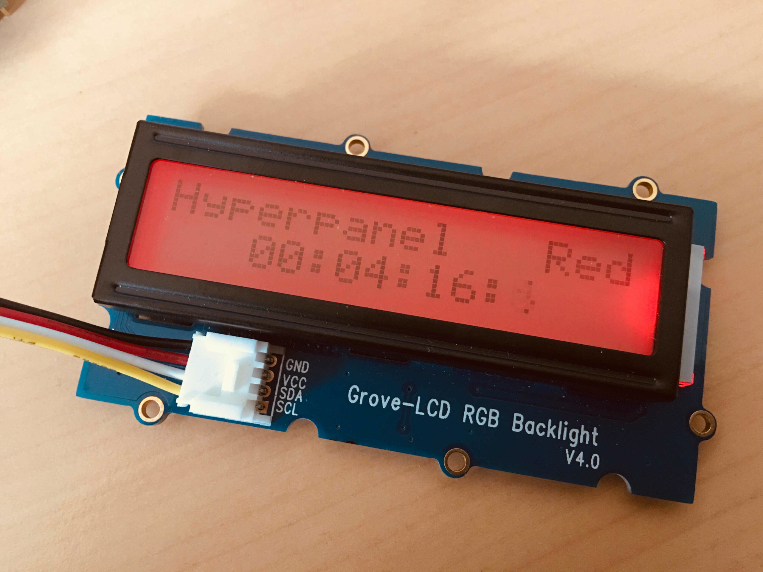
Application running – Red screen
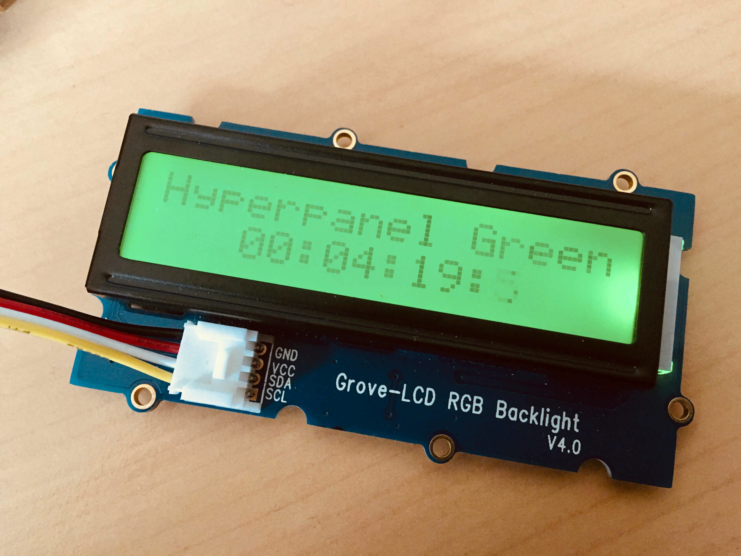
Application running – Green screen
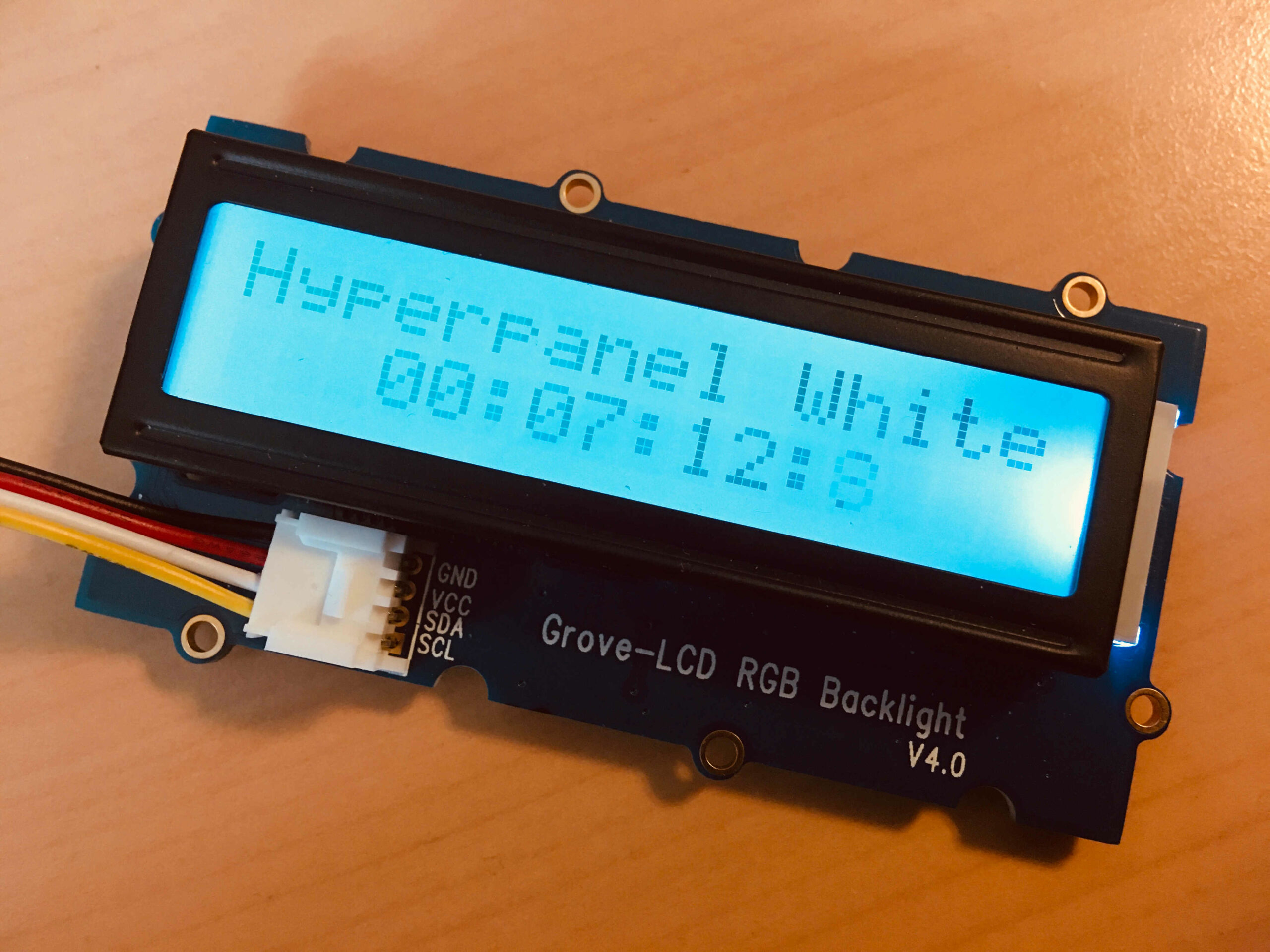
Application running – White screen
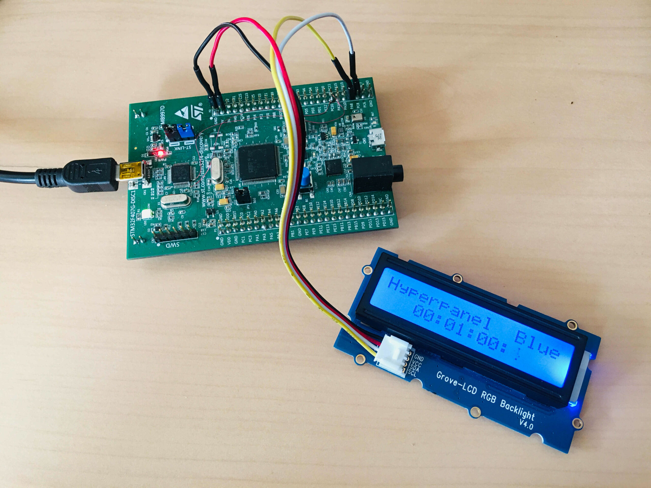
Full assembling
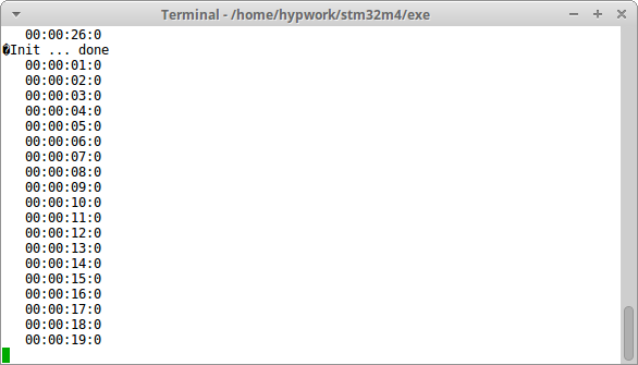
Application messages on serial port
Terminal
~/hypv100302/boards/stm32m4/exe >> hgdb
GNU gdb (7.10-1ubuntu3+9) 7.10
Copyright (C) 2015 Free Software Foundation, Inc.
License GPLv3+: GNU GPL version 3 or later <http://gnu.org/licenses/gpl.html>
This is free software: you are free to change and redistribute it.
There is NO WARRANTY, to the extent permitted by law.  Type "show copying"
and "show warranty" for details.
This GDB was configured as "--host=x86_64-linux-gnu --target=arm-none-eabi".
Type "show configuration" for configuration details.
For bug reporting instructions, please see:
<http://www.gnu.org/software/gdb/bugs/>.
Find the GDB manual and other documentation resources online at:
<http://www.gnu.org/software/gdb/documentation/>.
For help, type "help".
Type "apropos word" to search for commands related to "word".

man                    Display again this manual
stm32m4                Send the reset halt command to openocd
armdisconnect          Deconnexion command
peek adr               Read and display  a 32 bit value at adr
poke adr val           Write a val 32 bits value at adr
poke_m adr msk val     Write bits in a 32 bits word with a mask
peekrange base o1 o2   Read 32 bits words from base+o1 to base+o2
affichb adr size       Print a memory area starting at adr
vmio n                 Display the tnote_evt_s debug table
int                    Display the tnote_it debug table
rte                    Return from interrupt
romload stm32m4 app    Write the app executable file in flash
rom stm32m4 app        Connect to target and load app dbg symbols
gpio bank n state      Set GPIO n (0-15) of bank (1-9) to 0/1
clock 0/1/2/3          Output SYSCLK/PLLI2S/HSE/PLL to MO2/PC9
(gdb) romload stm32m4 lcd_rgb
Open On-Chip Debugger 0.10.0+dev-00001-g0ecee83-dirty (2017-02-10-06:53)
Licensed under GNU GPL v2
For bug reports, read
    http://openocd.org/doc/doxygen/bugs.html
0x00002ee2 in ?? ()
target halted due to debug-request, current mode: Thread
xPSR: 0x01000000 pc: 0x00003158 msp: 0x10002000
auto erase enabled
target halted due to breakpoint, current mode: Thread
xPSR: 0x61000000 pc: 0x20000046 msp: 0x10002000
wrote 393216 bytes from file lcd_rgb.bin in 11.128943s (34.505 KiB/s)
(gdb)