This tutorial shows how to use an analog rotary potentiometer thru an Analog to Digital Converter (ADC), used as I2C device on the MB1225 evaluation kit.
- A STMicroelectronics discovery kit with STM32F769NI MCU, order code 32F769IDISCOVERY (name on PCB: STM32F769I-DISCO).
- USB 2.0 male to micro USB cable (supplied with evaluation kit).
- A full installation of an Hyperpanel OS release on a linux based PC including tools for flashing and debugging. This tutorial requires release V30.01.01 for MB1225 or higher. Hyperpanel OS releases are available for free in the “Download” section of the website.
- A Lunix PC with ARM gcc compiler, ARM gdb debugger and minicom installed.
- A text editor to edit or modify source codes (We are using vi in our demo).
- A ADS1115 Module 4 channels 16 bits I2C ADC (available on Amazon).
- An analog potentiometer. You can for exemple use the Gravity Analog Rotation Potentiometer Sensor for Arduino.
Hyperpanel OS V30.01.01 for MB1225 (hypv300101.zip) or higher, available in the Download section.
Binary file
– On www.tutorial.hyperpanel.com, select Download from the main menu.
– Download “Hyperpanel OS V30.01.01 for MB1225” or higher release for the MB1225 kit (hypv300101.zip).
– On yo ur PC Linux, copy and unzip the zip file in your root directory, for example:
cp hypv300101.zip /home/hyperpanel
cd /home/hyperpanel
unzip hypv300101.zip
– With a text editor, update hhome environment variable in the stm32m7 file:
cd /home/hyperpanel/hypv300101/shells
vi stm32m7
Update the first line, according to your root directory:
export hhome=/home/hyperpanel/hypv300101
– Save this file and an execute the command:
source stm32m7
– From this tutorial, use the button “Binary file” to download the zip file containing the binary. Unzip this file:
unzip hpos-tuto412-bin.zip
– Copy this binary file in HyperPanelOS release:
cp potentiometer.bin ~/hypv300101/boards/stm32m7/exe
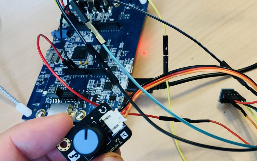
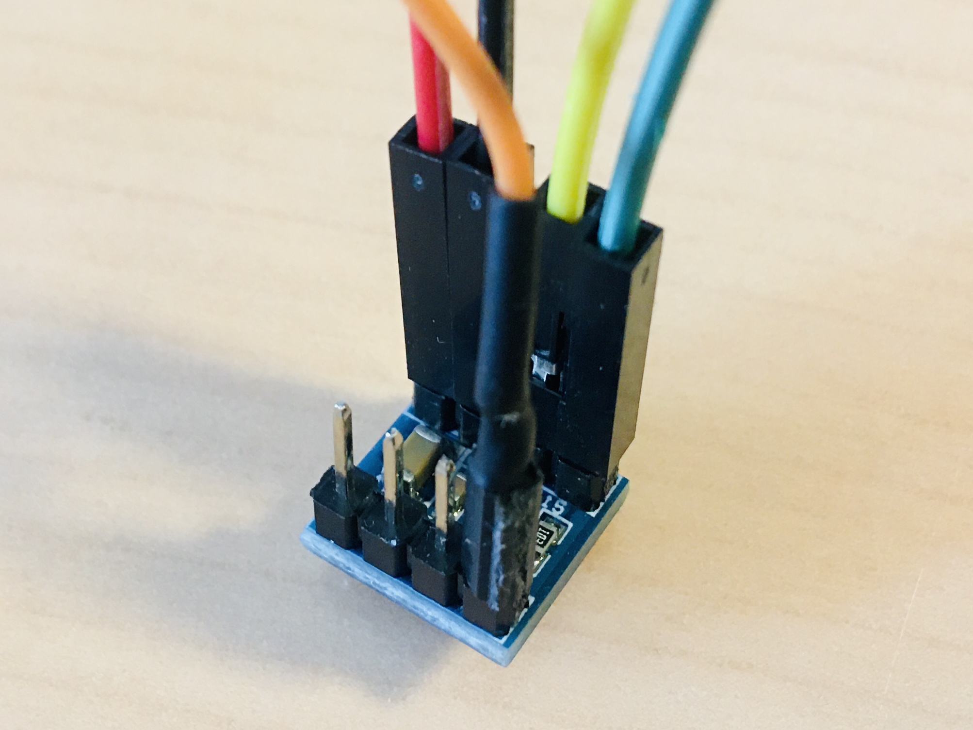
– Connect the analog rotary sensor data signal (orange wire) to pin 0 of the ADC (see image. Connect the analog rotary sensor power and ground(red and black wires) to the MB1225. Connect the ADC (power and data signals to the MB1225).
POTENTIOMETER ADC MB997D SIGNAL WIRE
Signal <------------> in0                           ADC_IN   Orange
Power <-----------------------------> CN11/3V3/4    Power    Red
Ground <----------------------------> CN11/GND/6    Ground   Black
                      SCL <---------> CN9/10/D15    I2C_SCL  Yellow
                      SDA <---------> CN9/ 9/D14    I2C_SDA  Green
                      VCC <---------> CN9/ 8/AVDD   Power    Red
                      GND <---------> CN9/ 7/GND    Ground   Black
– Connect the MB1225 board to a USB port on your Linux PC using the USB cable supplied with the board. Wait for a window to appear, then close it.
– Open a Terminal window and run minicom to get access to the Hyperpanel OS serial port and to the application messages:
minicom -D /dev/ttyACM0 -b 115200
– Open another Terminal window on your computer and enter the following commands:
cd ~/hypv300101/shells
source stm32m7
exe
– Upload software to the board:
hgdb
romload stm32m7 potentiometer
You should see messages similar to these:
Open On-Chip Debugger 0.10.0+dev-00001-g0ecee83-dirty (2017-02-10-06:53)
Licensed under GNU GPL v2
For bug reports, read
http://openocd.org/doc/doxygen/bugs.html
0x00002eca in ?? ()
target halted due to debug-request, current mode: Thread
xPSR: 0x01000000 pc: 0x00003140 msp: 0x20002000
auto erase enabled
target halted due to breakpoint, current mode: Thread
xPSR: 0x61000000 pc: 0x20000046 msp: 0x20002000
wrote 393216 bytes from file potentiometer.bin in 11.261815s (34.098 KiB/s)
potentiometer.elf: No such file or directory.
Wait until the flashing operation is complete (approx. 30 seconds). The last message (potentiometer.elf: No such file or directory) is normal.
– You can now press on the reset button (black button) of the MB1225. Hyperpanel OS and the application will start. You can turn the analog rotation sensor. The digital converter value, from 0 to 127 appears on the serial port.
To go further
If you want to edit the source code, write modifications, compile, link, etc., here’s how to do it :
- From this tutorial, use the button “Source code” to download the zip file containing the source file. Unzip this file:
unzip hpos-tuto412-source.zip
- Copy this source code in HyperPanelOS release:
cp potentiometer.c ~/hypv300101/user/stm32app
- Copy the link file in Hyperpanel release:
cp petentiometer.lst ~/hypv300101/boards/stm32m7/exe
- You can edit and make any modifications you want in the source file. For example, you can modify the calibration of the [0,…,127] values by changing the max value at the line 189 of the source file.
cd ~/hypv300101/user/stm32app
vi potentiometer.c
- Save the source file.
- Compile the source file:
cd ~/hypv300101/user/stm32app
cmm potentiometer
- Call the linker to create the new binary file:
exe
lhypos potentiometer
- You can now upload this new binary to the board, in the same way as in the previous Installation chapter.
Potentiometer :
- The potentiometer send continuous voltage tension from [0v,…,3.3V]. This tension is converted by the ADC to a 16-bit value. The app is just a main loop who read this 16-bit value (I2C register) each 100 ms.
- At the position corresponding to minimum value, the potentiometer deliver 0V. At the maximum value, the potentiometer delivers 3.3V so we have to calibrate the ADC settings to this range.
Analog to Digital Converter (ADC) :
- The ADC use the potentiometer as analog input signal et send digital output data to the MB997D via I2C interface.
- The ADC converter include one single I2C device. There is 4 analog input channels. In this app we use Input 0 (data signal). This configuration is setted with bit 14-12 of the configuration register.
- We select FS=+/-4.096V for the PGA (Programmable gain amplifier) of the ADC (cf. datasheet of the ADC) to fit with range (0-3.3V] of the potentiometer.
2C Interface :
- I2C address are 0x90 (write) and 0x9 (read).
- The ADS1115 have a configuration register. The app write de configuration in the initialisation step, and read the configuration register to check that the write operation is ok. Configuration register is set as follow (see datasheet page 18/19/20).
bit 15    Operational status                   0 (default)
bit 14-12 Multiplexer config - INp=0 INn=GND 100 (INp=0 Nn=GND)
bit 11-9  Gain amplifier FS= +/- 6.144V      001 (+/-4.06V)
bit 8     Device operating mode                0 (continuous)
bit 7-5   Data rate 111 (860SPS)
bit 4     Comparator mode - Traditional        0 (default)
bit 3     Comparator polarity - Active low     0 (default)
bit 2     Nn-latching comparator               0 (default)
bit 1-0   Disable comparator                  11 (default)
0100001011100011 = 0x42E3Documents
Links
Potentiometer is running
hypos-tuto412-source
/*
**  potentiometer.c - Sample code for HyperpanelOS ========================  **
**                                                                           **
**  This simple code is located into the application container, it is run    **
**  by the VMK sub-operating system. On the other hand, the I/O container    **
**  runs all the drivers that are VMIO finite state machines.                **
**                                                                           **
**  The goal of this small app is to use a analog potentiometer.             **
**                                                                           **
**  =======================================================================  **
*/


/* Documentation for I2C devices --------------------------------------------

   Product used :

   - Ben-Gi Mini ADS115 Module 4 channels 16 bits I2C ADC
     www.amazon.fr/gp/product/B07PK1Z5H1
     datasheet-ads115.pdf - Texas Instruments
                            16-bit Ananlog-to-Figital Converter

   - Rotation Sensor-L V2 from LattePanda Starter Sensor Set
     www.lattepanda.com
     wiki.dfrobot.com/Analog_Rotation_Sensor_V2__SKU__DFR0058_#target_4

    Potentiometer:

    - The potentiometer send continuous voltage tension from [0v,3.3V] this
      tension is converted by the ADC to a 16-bit value. The app is just a
      main loop who read this 16-bit value (I2C register) each 100 ms.

    - At the position corresponding to minimum value, the potentiometer deliver
      0 V. At the maximum value, the potentiometer delivers 3.3V so we have
      to adapt the ADC settings to this range.

    Analog to Digital Converter (ADC):

    - The ADC use the potentiometer as analog input signal et send digital
      output data to the Pyboard via I2C interface.

    - The ADC converter include one single I2C device. There is 4 analog
      input channels. In this app we use Input 0 (data signal). This
       configuration is setted with bit 14-12 of the configuration register.

    -  We select FS=+/-4.096V for the PGA (Programmable gain amplifier) of the
       ADC (cf.  datasheet of the ADC) to fit with range (0-3.3V] of the
       potentiometer.

    I2C Interface:

    - I2C address are 0x90 (write) and 0x9 (read).

    - The ADS1115 have a configuration register. The app write de configuration
      in the initialisation step, and read the configuration register to check
      that the write operation is ok. Configuration register is set as follow
      (cf.  datasheet page 18/19/20).

      bit 15       Operational status                      0   (default)
      bit 14-12    Multiplexer config - INp=0 INn=GND    100   (INp=0 Nn=GND)
      bit 11-9     Gain amplifier FS= +/- 6.144V         001   (+/-4.06V)
      bit 8        Device operating mode                   0   (continuous)
      bit 7-5      Data rate                             111   (860SPS)
      bit 4        Comparator mode - Traditional           0   (default)
      bit 3        Comparator polarity - Active low        0   (default)
      bit 2        Nn-latching comparator                  0   (default)
      bit 1-0      Disable comparator                     11   (default)

                                            0100001011100011 = 0x42E3


*/
/* Include files and external reference -------------------------------------*/

#include <hypos.h>                     // Hyperpanel OS basic interfaces.
#include <drv_asy.h>                   // Prototype of "asy_write()".
#include <drv_i2c.h>                   // Prototype of "i2c_*()".


/* Internal defines of this module ------------------------------------------*/

#define  TICK                 1000     // Code for tick event.

#define ADC_AD_W              0x90     // I2C dev address - ADC (write)
#define ADC_AD_R              0x91     // I2C dev address - ADC (read)

#define CONVERSION_REG        0x00     // I2C register - Converted value
#define CONFIG_REG            0x01     // I2C register - Configuration

#define INIT                     0     // I2C command - ADC initialisation


/*  Internal global variables of this module --------------------------------*/

    static unsigned int idto         ; // Timer identifier.


/* INIT command .............................................................*/

    static const char init[]         = // I2C command - ADC initialisation
      {

/*    Length-1, Address, Control byte, Data byte                             */

      3, ADC_AD_W , CONFIG_REG       , // Write the configuration register
                    0x42, 0xE3       , // Cf. datasheet page 19)
      0                              , // End of command set
      }                              ; //

    static char   *command[] =         // I2C commands table
      {                                //
        (char*)&init                 , // I2C command - INIT
        (char*)0                       // End of list
      }                              ; //

/*  Prototypes --------------------------------------------------------------*/

    static int  loop_app_task(void*) ; // Prototype
    static int  wait_evt(void)       ; // Prototype
    static void set_command(int)     ; // Prototype


/*  Beginning of the code ---------------------------------------------------

    loop_app_tsk         Application entry point
*/

/*  Procedure loop_app_tsk --------------------------------------------------

    Purpose : This is our task main loop.
*/

int loop_app_tsk (void *param)
  {
    int             ev = TICK        ; // Our event
    char            mess[16]         ; // Message to be sent on ASY0
    unsigned char   frame[16]        ; // I2C read frame
    int             ret = 0          ; // Return procedure code


/* Step 1 - Start a timer that will send an event every second ..............*/

    set_uto(CLOCK      ,               // Timer mode: clock
            100        ,               // Duration in milliseconds
            TICK , 0   ,               // Event code and reserve field
            &idto     );               // Timer identifier


/* Step 2 - ADC initialisation ..............................................*/

    asy_write(0,(unsigned char*)"Init ... ",9);

    set_command(INIT)                ; // ADC initialization

    asy_write(0,(unsigned char*)"done\r\n",6);

    ret = i2c_read(                    // Just for checking, read the register
                0                    , // I2C controller number
                0                    , // I2C protocol code
                ADC_AD_R             , // Target I2C read address
                CONFIG_REG           , // Sub-address value
                frame                , // Receive data buffer address
                2                    , // Count of bytes to be read
                0                   ); // List of option flags

    hsprintf(mess,
        "Configuration register 0x%02x%02x (%d)\r\n",
                              frame[0],frame[1],ret);

    asy_write(0                      , // Write on ASY0 the value of the
        (unsigned char*)mess         , // configuration register.
                 strlen(mess)       ); // Count of bytes to be sent


/* Step 3 - Main loop .......................................................*/

    wait_ev :                          // Beginning of loop label

    if ( ev == TICK )                  // If the event is the tick event
      {                                //
        frame[0]=0                   ; // Reset frame.
        frame[1]=0                   ; // Reset frame.

        ret = i2c_read(                // Read current value get from the ADC
                    0                , // I2C controller number
                    0                , // I2C controller code
                    ADC_AD_R         , // Target I2C read address
                    CONVERSION_REG   , // Sub-address value
                    frame            , // Receive data buffer address
                    2                , // Count of bytes to be read
                    0               ); // List of option flags

        frame[0]= frame[0] EQ 0xFF ? 0x00 : frame[0];

        hsprintf(mess                , // Message with the 16-bit value.

           "ADC register: 0x%02x%02x -> Button value %03d\r\n",

                   frame[0],frame[1]       , // Conversion Voltage -> [0,127]
                  (frame[0]*0x7f)/0x5c,ret); // (0x5c max value read from
                                             // register with this model of
                                             // potentiometer).

        asy_write(0                  , // Write on ASY0
              (unsigned char*)mess   , // the "mess" message
              strlen(mess)          ); // Count of bytes to be sent
      }

      ev = wait_evt()                ; // Unschedule until an event is received
      goto wait_ev                   ; // Wait for the next event

      return  0                      ; // Return code of the procedure
    }

/*  Procedure wait_evt ------------------------------------------------------*/
/*
    Purpose : Unschedule until the next event is received, whatever it is.
*/

static int wait_evt (void)
  {
    unsigned int waitlist[1][3]      ; // Parameter of "waitevt_task"

/*****************************************************************************
 * Step 1 : Build a list with one WAIT_CODEINT entry that will accept all    *
 * ------   the event codes ranging from 0 to 20000. Then call               *
 *          "waitevt_task", we will be unscheduled until the next event will *
 *          be received                                                      *
 *****************************************************************************/

    waitlist[0][0]  = WAIT_CODEINT   ; // All events with
    waitlist[0][1]  = 0              ; // a code between 0
    waitlist[0][2]  = 20000          ; // and 20000

    waitevt_task(waitlist ,            // Address of waiting list
                 1        ,            // Size of "waitlist[]"
                 0        ,            // maximum waiting time = no
                 0        )          ; // Do not purge previous events

/*****************************************************************************
 * Step 2 : Here we are scheduled again. The VMK has written into its        *
 * ------   global variable "task_evt" a copy of the event that has          *
 *          scheduled us again.                                              *
 *****************************************************************************/

    return task_evt.code             ; // Return event code
  }


/*  Procedure set_command ---------------------------------------------------*/
/*
    Purpose : Send a set of commands to I2C devices.
*/

static void set_command(int cmd)
  {
    i2c_write(                         // Send I2C command
        0                            , // Controller number
        PRO_I2C_DEV                  , // Protocol code
       -1                            , // Target address unused with FLG_MULTI
        0                            , // Target sub-address
        (unsigned char*)command[cmd] , // Command
        sizeof(command[cmd])         , // Count of bytes unused with FLG_MULTI
        FLG_MULTI                   ); // Several commands in I2C buffer
  }
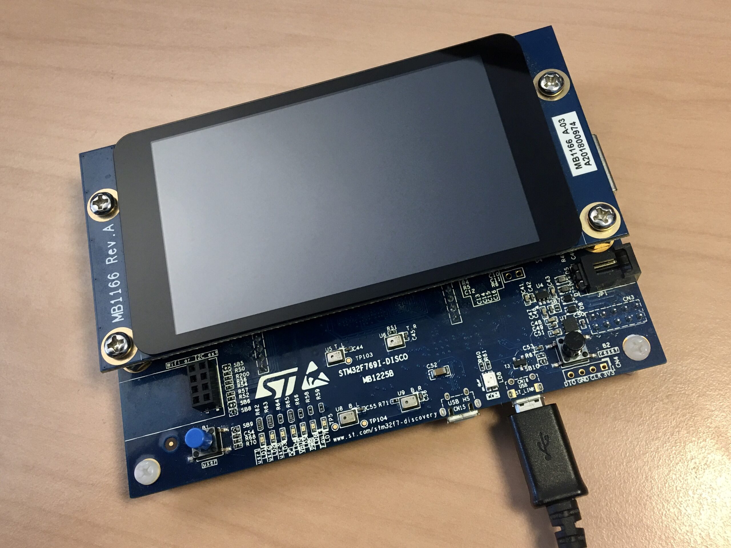
The 32F769IDISCOVERY / MB1225 evaluation kit
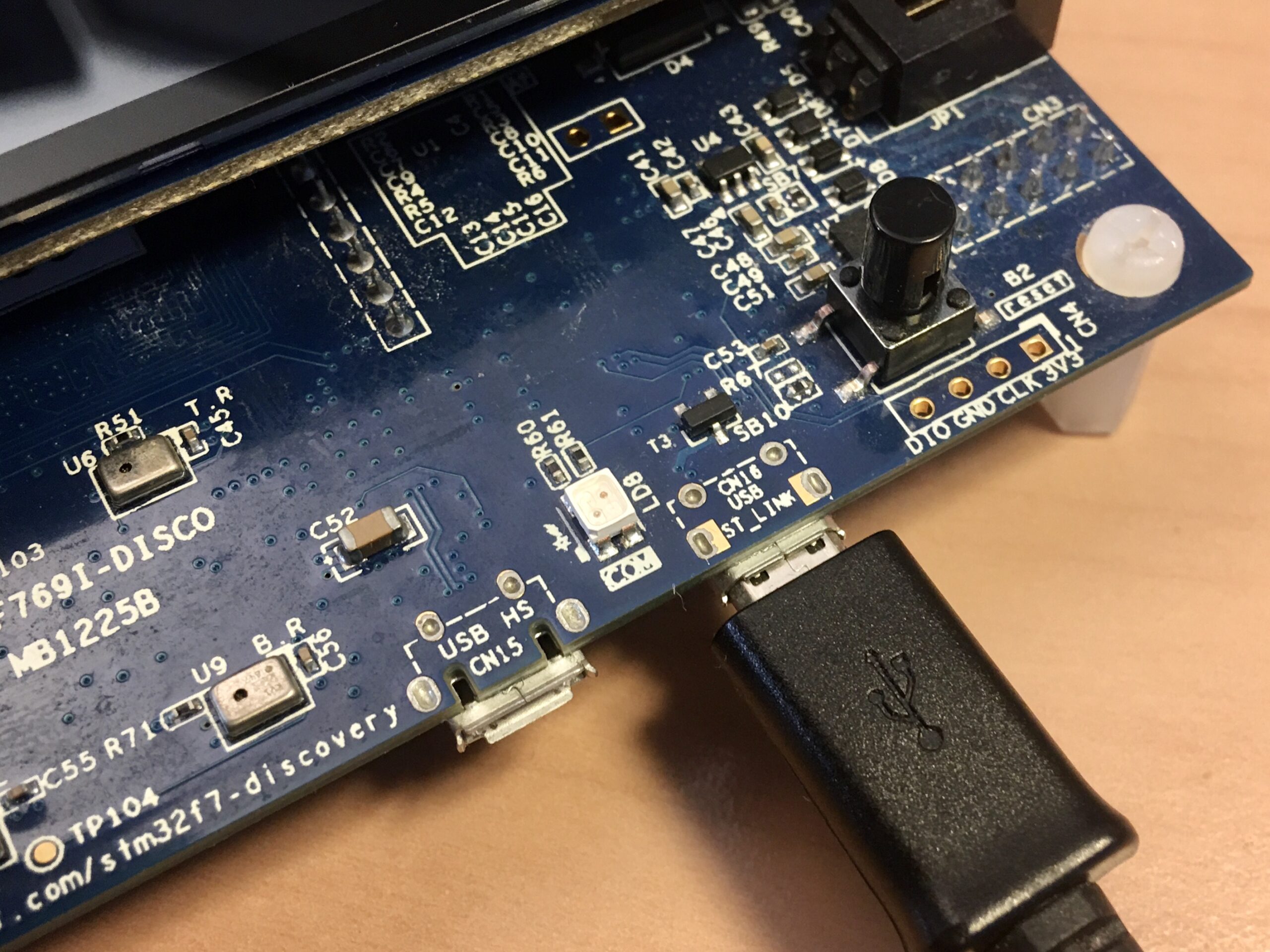
ST-LINK USB connector to the computer
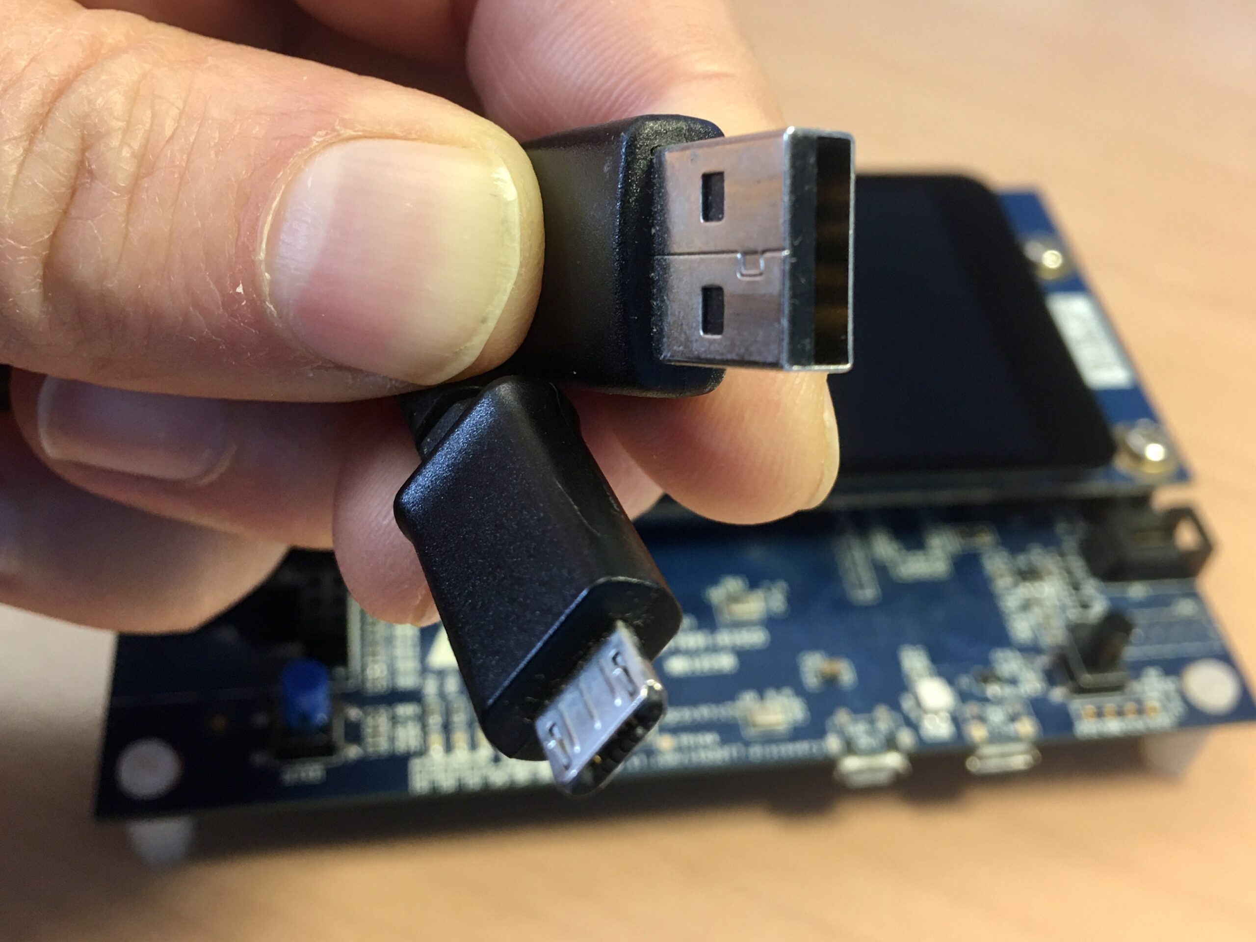
USB cable
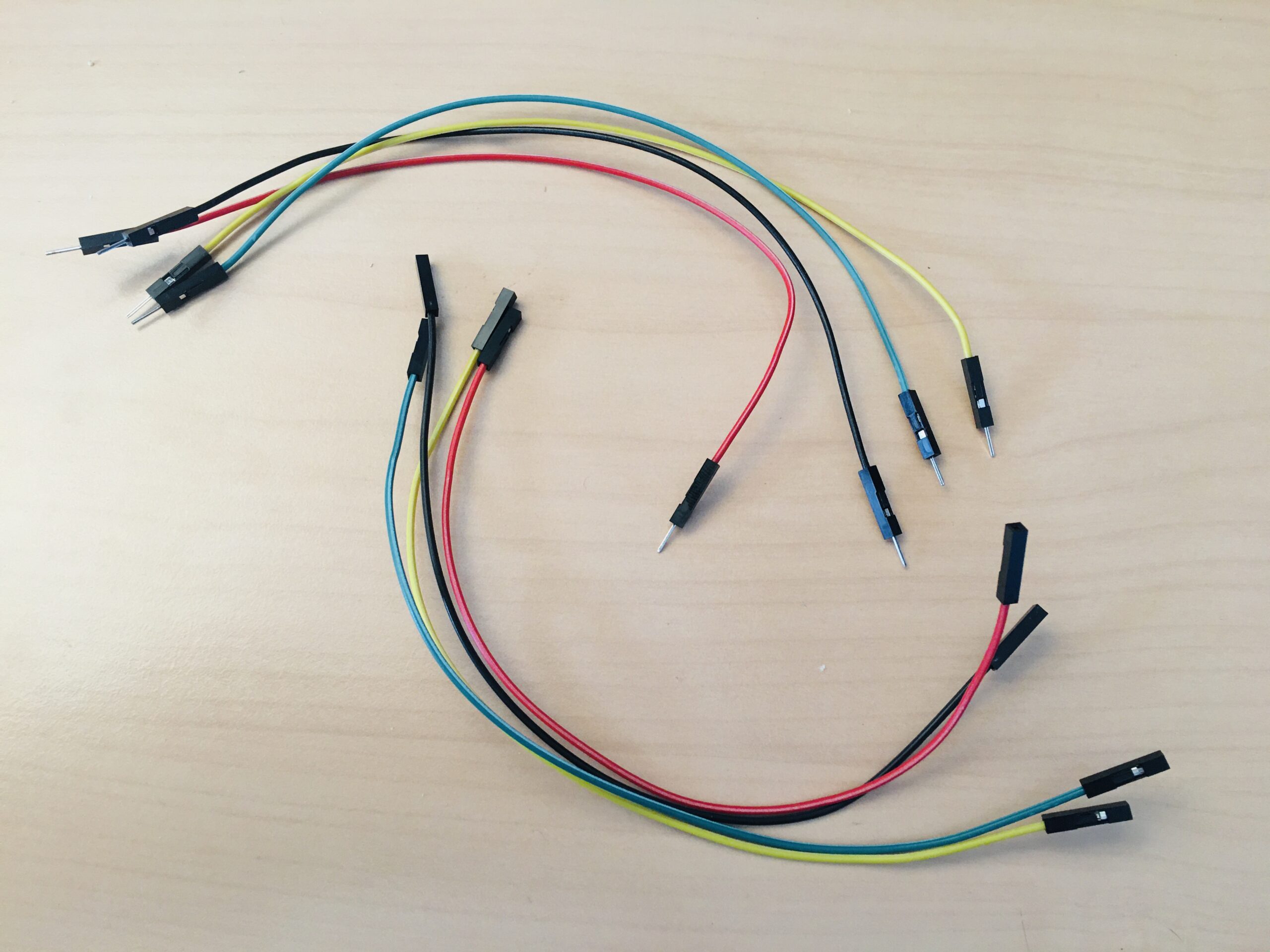
Wires for I2C device / Arduino connector
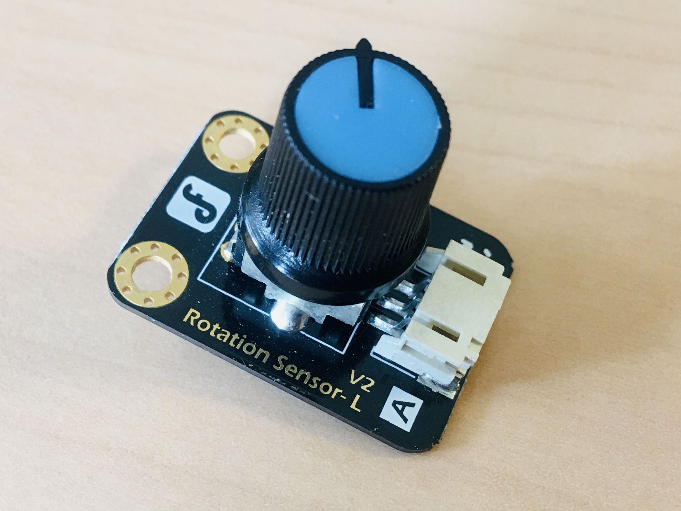
Analog potentiometer – LattePanda Rotation Sensor V2
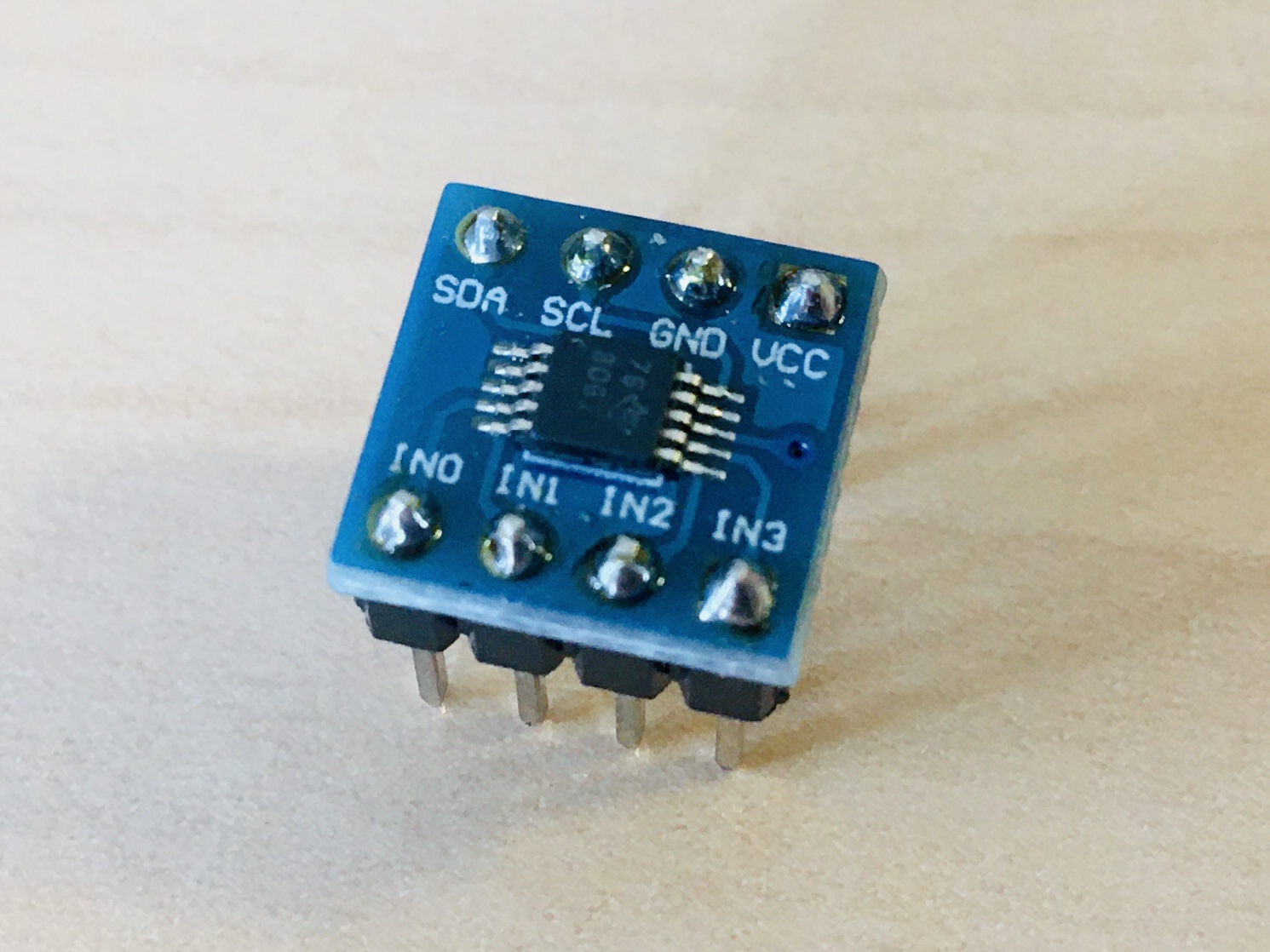
Analog to Digital Converter – ADC ADS1115
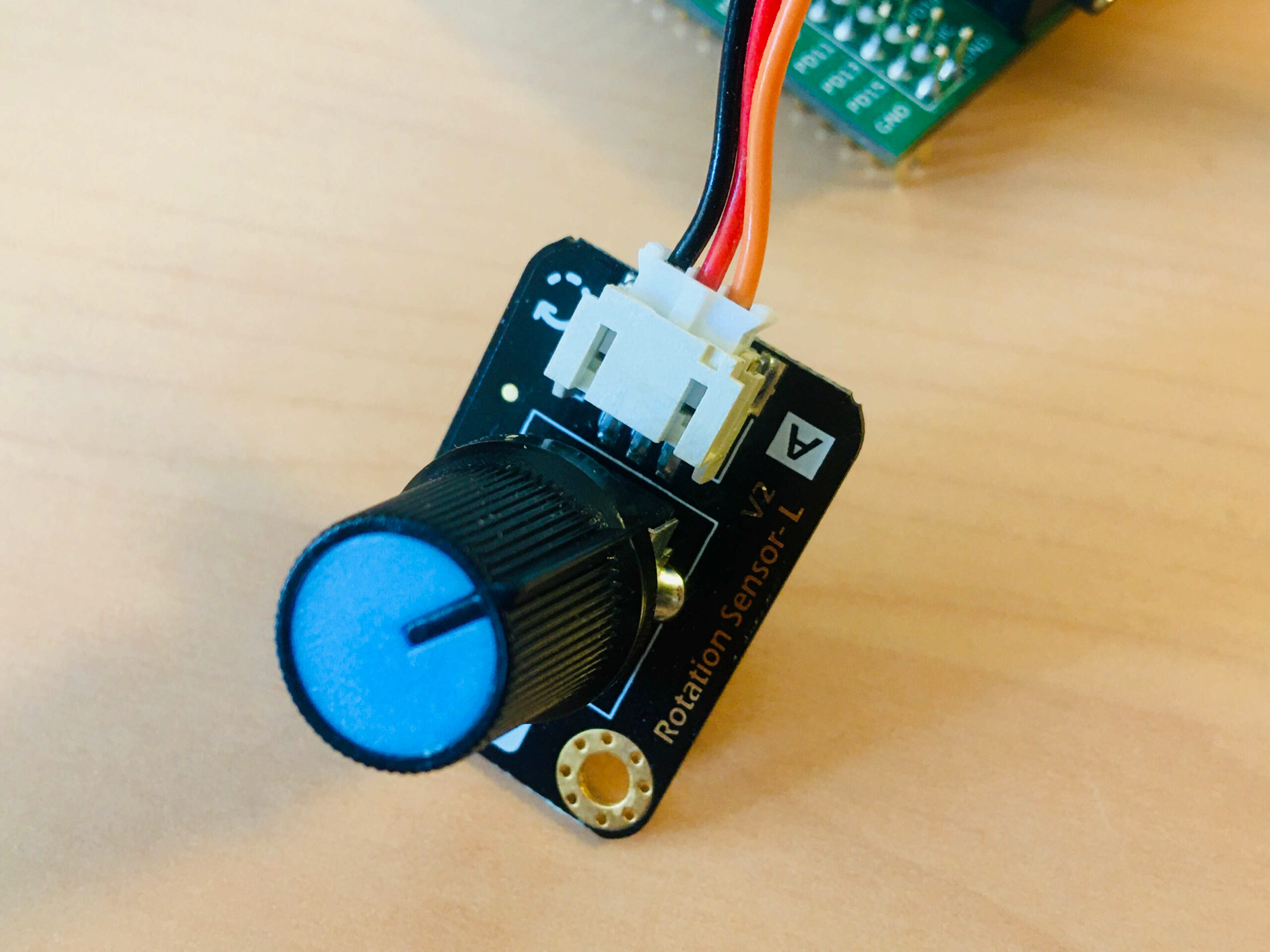
How to connect the potentiometer
How to connect the ADC
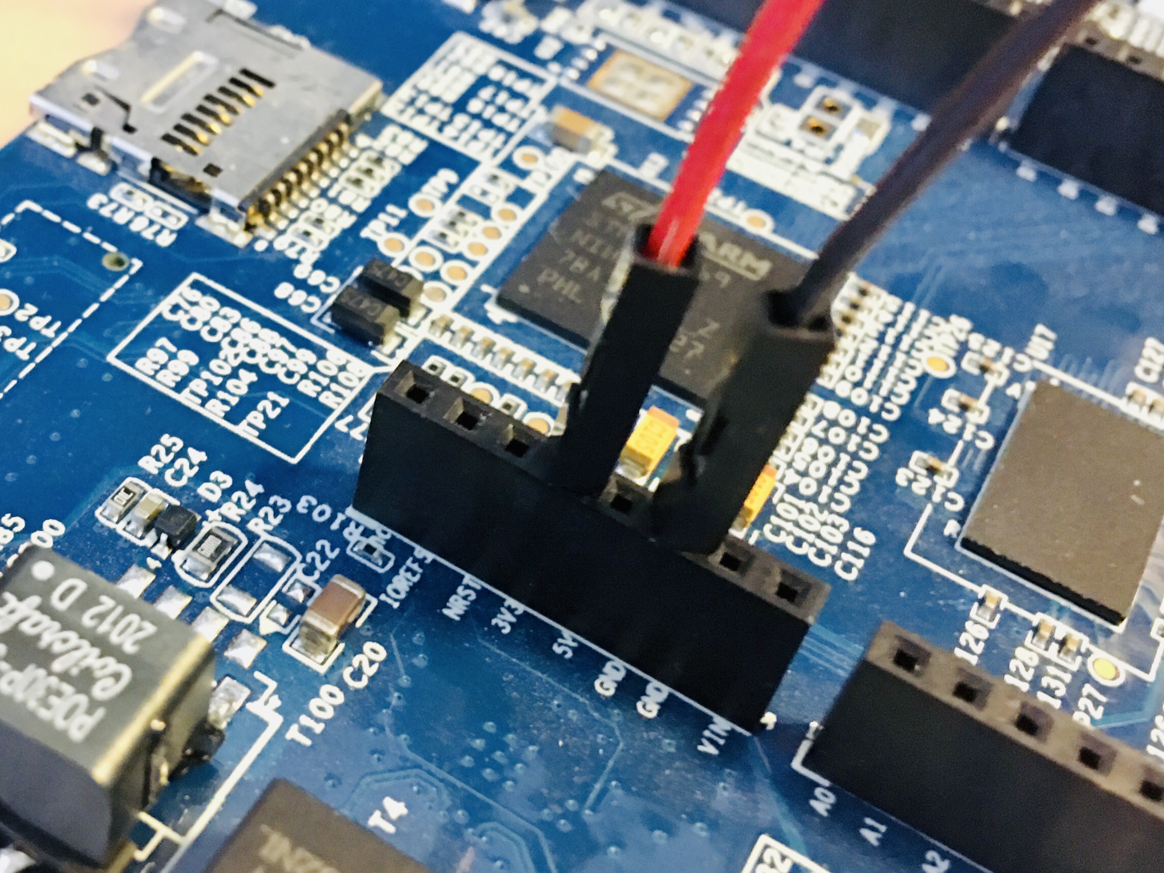
How to connect power devecies to the MB1225
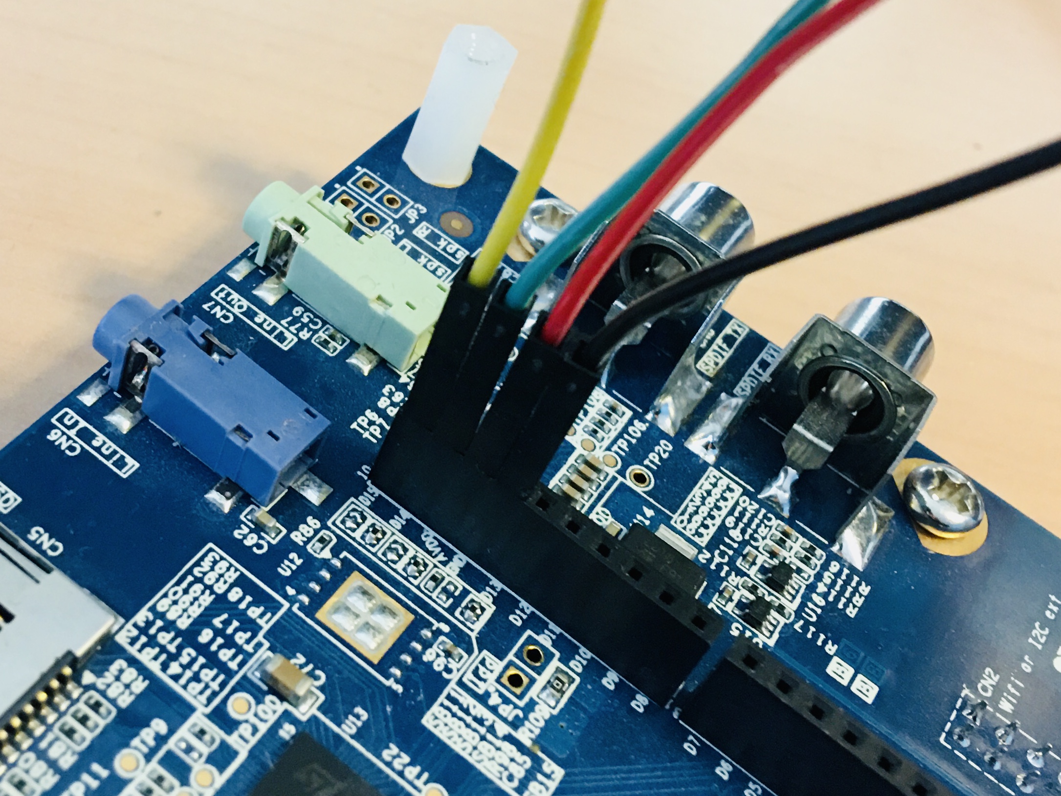
How to connect I2C of ADC to the MB1225
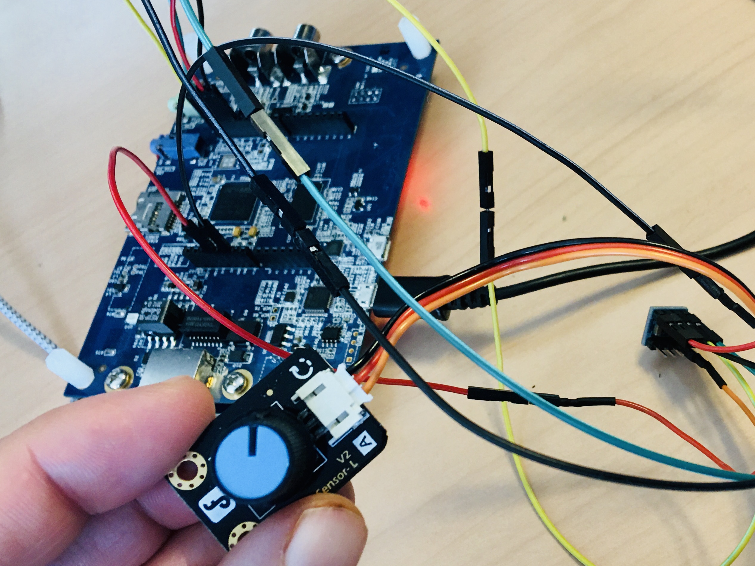
Full hardware ready to use
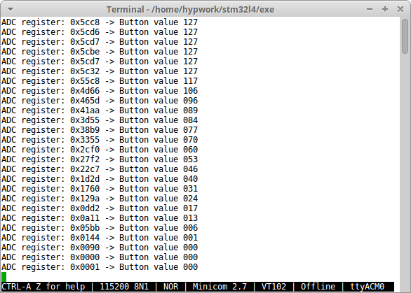
Application messages on serial port
Terminal
 ~/hypv100302/boards/stm32m4/exe >> hgdb
GNU gdb (7.10-1ubuntu3+9) 7.10
Copyright (C) 2015 Free Software Foundation, Inc.
License GPLv3+: GNU GPL version 3 or later <http://gnu.org/licenses/gpl.html>
This is free software: you are free to change and redistribute it.
There is NO WARRANTY, to the extent permitted by law.  Type "show copying"
and "show warranty" for details.
This GDB was configured as "--host=x86_64-linux-gnu --target=arm-none-eabi".
Type "show configuration" for configuration details.
For bug reporting instructions, please see:
<http://www.gnu.org/software/gdb/bugs/>.
Find the GDB manual and other documentation resources online at:
<http://www.gnu.org/software/gdb/documentation/>.
For help, type "help".
Type "apropos word" to search for commands related to "word".

man                    Display again this manual
stm32m4                Send the reset halt command to openocd
armdisconnect          Deconnexion command
peek adr               Read and display  a 32 bit value at adr
poke adr val           Write a val 32 bits value at adr
poke_m adr msk val     Write bits in a 32 bits word with a mask
peekrange base o1 o2   Read 32 bits words from base+o1 to base+o2
affichb adr size       Print a memory area starting at adr
vmio n                 Display the tnote_evt_s debug table
int                    Display the tnote_it debug table
rte                    Return from interrupt
romload stm32m4 app    Write the app executable file in flash
rom stm32m4 app        Connect to target and load app dbg symbols
gpio bank n state      Set GPIO n (0-15) of bank (1-9) to 0/1
clock 0/1/2/3          Output SYSCLK/PLLI2S/HSE/PLL to MO2/PC9
(gdb) romload stm32m4 potentiometer
Open On-Chip Debugger 0.10.0+dev-00001-g0ecee83-dirty (2017-02-10-06:53)
Licensed under GNU GPL v2
For bug reports, read
    http://openocd.org/doc/doxygen/bugs.html
0x00012a3a in ?? ()
target halted due to debug-request, current mode: Thread
xPSR: 0x01000000 pc: 0x00003140 msp: 0x10002000
auto erase enabled
target halted due to breakpoint, current mode: Thread
xPSR: 0x61000000 pc: 0x20000046 msp: 0x10002000
wrote 393216 bytes from file potentiometer.bin in 11.165994s (34.390 KiB/s)
Cannot access memory at address 0x8000f8d0
(gdb)