This tutorial explains how to use an I2C Encoder from Duppa with an illuminated RGB rotary & push button.
- A STMicroelectronics discovery kit with STM32F407VG MCU, order code STM32F407-DISC1 (replaces STM32F4DISCOVERY).
- USB 2.0 male to micro B cable (supplied with evaluation kit).
- A full installation of an Hyperpanel OS release on a linux based PC including tools for flashing and debugging. This tutorial requires release V10.03.02 for MB997D or higher. Hyperpanel OS releases are available for free in the “Download” section of the website.
- A Lunix PC with ARM gcc compiler, ARM gdb debugger and minicom installed.
- A text editor to edit or modify source codes (We are using vi in our demo).
- DuPPa I2C Encoder V2.1 from www.duppa.net.
Hyperpanel OS V10.03.02 for MB997D (hypv100302.zip) or higher, available in the Download section.
Binary file
Hardware rework
The evaluation kit uses a USB port for power and debugger access. This connector is managed by a ST-LINK part, controlled by a STM32F103CBT6 (U2 on the board). The ST-LINK supports a virtual COM port on U2 pin 12 (ST-LINK_TX) and U2 pin 13 (ST-LINK_RX) but these pins are not connected to the USART of the STM32F407. To access to serial port for traces and messages, the solution is to use two flying wires to connect ST-LINK virtual COM port to the ASY1 HyperPanelOS serial port (see image):
U2 (STM32F103CBT6)                          P2 (CONNECTOR)
PIN 12 (ST-LINK_TX) <---------------------> PC11 (ASY1_RX)
PIN 13 (ST-LINK_RX) <---------------------> PC10 (ASY1_TX)
1. On www.tutorial.hyperpanel.com, select Download from the main menu.
2. Download “Hyperpanel OS V10.03.02 for MB997D” or higher release for the MB997D kit.
3. On your PC Linux, copy and unzip the zip file in your root directory, for example:
cp hypv100302.zip /home/hyperpanel
cd /home/hyperpanel
unzip hypv100302.zip
4. With a text editor, update hhome environment variable in the stm32m4 file:
cd /home/hyperpanel/hypv100302/shells
vi stm32m4
Update the first line, according to your root directory:
export hhome=/home/hyperpanel/hypv100302
5. Save this file and an execute the command:
source stm32m4
6. From this tutorial, use the button “Binary file” to download the zip file containing the binary. Unzip this file:
unzip hpos-tuto313-bin.zip
7. Copy this binary file in HyperPanelOS release:
cp potentiometer.bin ~/hypv100302/boards/stm32m4/exe
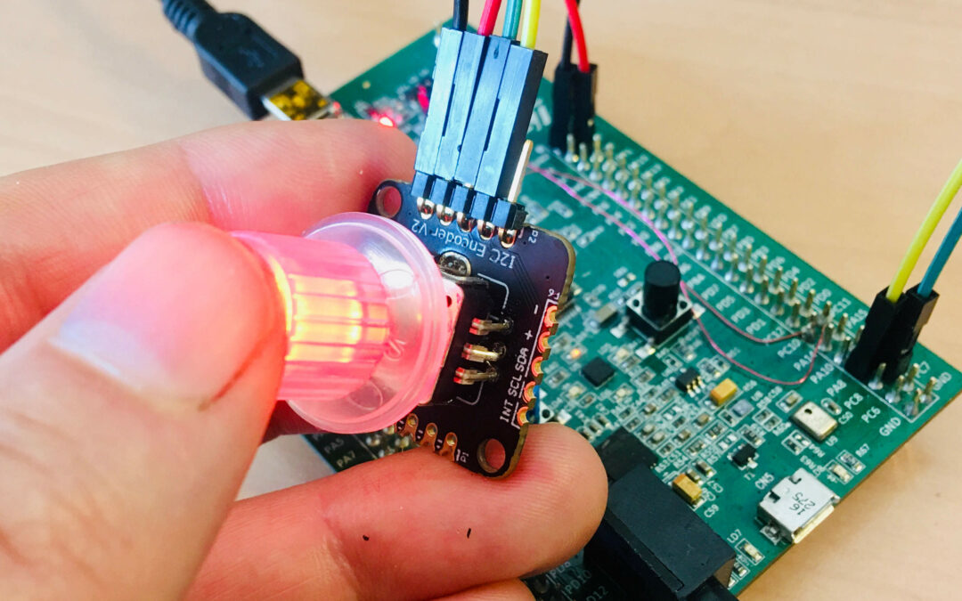
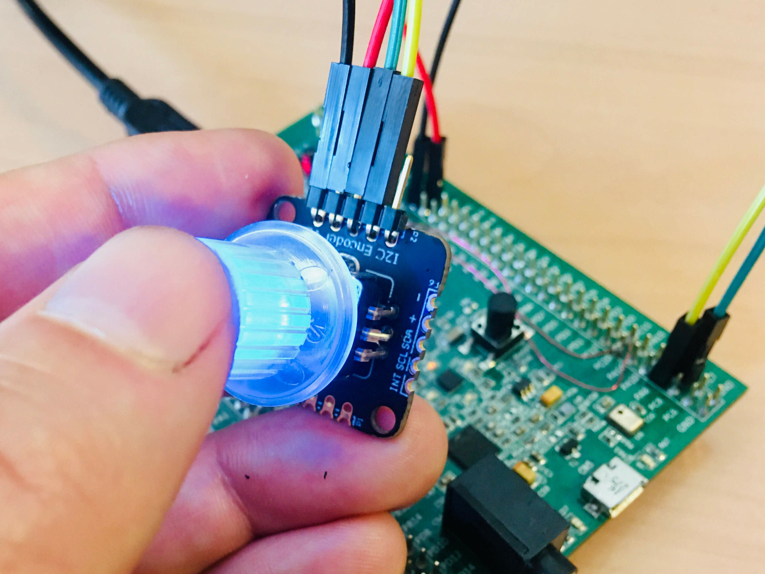
8. Connect the analog rotary sensor data signal (orange wire) to pin 0 of the ADC (see image. Connect the analog rotary sensor power and ground(red and black wires) to the MB997D. Connect the ADC (power and data signals to the MB997D).
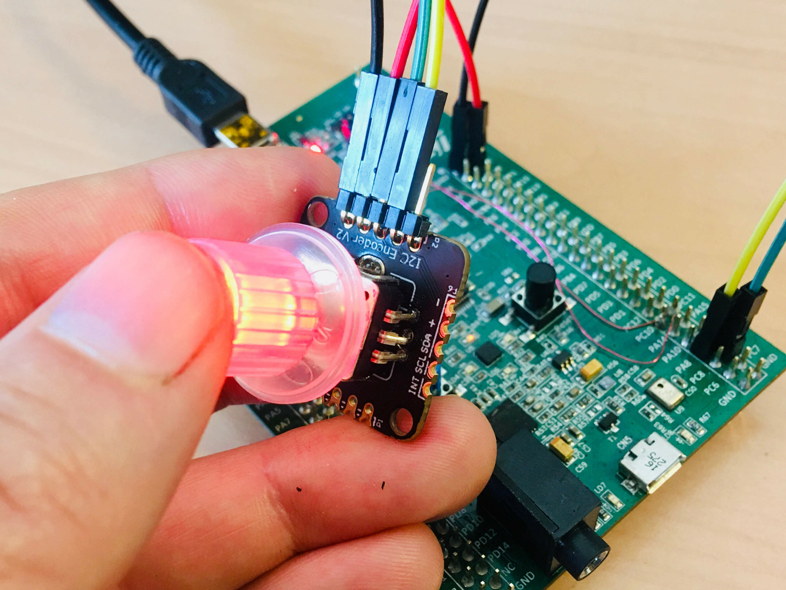
ENCODER         MB997D   SIGNAL   WIRE

VCC <---------> 3V       Power     Red
GND <---------> GND      Ground    Black
SDA <---------> PC9      I2C_SDA   Green
SCL <---------> PA8      I2C_SCL   Yellow
9. Connect the MB997D board to a USB port on your Linux PC using the USB cable supplied with the board. Wait for a window to appear, then close it.
10. Open a Terminal window and run minicom to get access to the Hyperpanel OS serial port and to the application messages:
minicom -D /dev/ttyACM0 -b 115200
11. Open another Terminal window on your computer and enter the following commands:
cd ~/hypv100302/shells
source stm32m4
exe
12. Upload software to the board:
hgdb
romload stm32m4 encoder
You should see messages similar to these:
Open On-Chip Debugger 0.10.0+dev-00001-g0ecee83-dirty (2017-02-10-06:53)
Licensed under GNU GPL v2
For bug reports, read
http://openocd.org/doc/doxygen/bugs.html
0x00002ed6 in ?? ()
target halted due to debug-request, current mode: Thread
xPSR: 0x01000000 pc: 0x0000314c msp: 0x10002000
auto erase enabled
target halted due to breakpoint, current mode: Thread
xPSR: 0x61000000 pc: 0x20000046 msp: 0x10002000
wrote 393216 bytes from file encoder.bin in 11.153441s (34.429 KiB/s)
encoder.elf: No such file or directory.
(gdb)
Wait until the flashing operation is complete (approx. 30 seconds). The last message (encoder.elf: No such file or directory) is normal.
13. You can now press on the reset button (black button) of the MB997D. Hyperpanel OS and the application will start. You can turn the encoder to see value encoding on the serial port, and you can press the button to see color changing.
To go further
If you want to edit the source code, write modifications, compile, link, etc., here’s how to do it :
- From this tutorial, use the button “Source code” to download the zip file containing the source file. Unzip this file:
unzip hpos-tuto313-source.zip
- Copy this source code in HyperPanelOS release:
cp encoder.c ~/hypv100302/user/stm32app
- Copy the link file in Hyperpanel release:
cp encoder.lst ~/hypv100302/boards/stm32m4/exe
- You can edit and make any modifications you want in the source file.
cd ~/hypv100302/user/stm32app
vi encoder.c
- Save the source file.
- Compile the source file:
cd ~/hypv100302/user/stm32app
cmm encoder
- Call the linker to create the new binary file:
exe
lhypos encoder
- You can now upload this new binary to the board, in the same way as in the previous Installation chapter.
This tutorial uses the I2C Encoder V2.1 from www.duppa.net. This is a small board where we can use a mechanical standard rotary encoder, or an illuminated RGB encoder. We use here a illuminated encoder. The Duppa device is an I2C device.
This tutorial uses the encoder for following basic operations:
- The range of generate value is fixed to [0,…,100].
- The encoder manages minimum value (0) and maximum value (100).
- The RGB light can be modified by pushing the button. Each time the push button is used, the color change (red, green, blue, red, green, blue, etc…). This can be use for example to trig several settings with only one button (select a parameter by button “press”, and tweaking values with rotary encoder).
- If the device dont answer, an error message is generated.
- The I2C Encoder has a series of 8 bit registers where it is possible to configure the parameters (RESET, button type, etc…), and four 32 bit of registers. These 32 bit registers are used for set and read the values of the encoder. The Encoder manages counter value, value of increment steps, maximum and minimum thresholds. Every time when the encoder rotates at least one step, the counter value increases or decreases according to the rotation direction by the value of the increment steps register.
- The encoder is an infinite rotary button. When the counter value is outside of the limit set by the thresholds registers, the counter value can be configured to be wrapped or stucked on the threshold value.
- The initialization sequence of the Encoder is :
2, DUPPA_AD , REG_GCONF , RESET       , // Reset (takes 400 us)
1, DUMMY_AD , 0xFF                    , // Tempo for reset
1, DUMMY_AD , 0xFF                    , // Tempo for reset
2, DUPPA_AD , REG_GCONF , RGB_ENCODER , // Set RGB encoder mode
2, DUPPA_AD , REG_CMAXB1 , 100        , // Set the max value
2, DUPPA_AD , REG_ISTEPB1, 1          , // Set incrementation value
0, 0 , 0 , 0                          , // End of command set
- Register map of the encoder is available in the datasheet, page 16.
- Configuration register used in the tutorial is described in the datasheet, page 17.
- Status register used (for “press” interrupt) in this tutorial is described in the datasheet, page 22.
Documents
Links
hypos-tuto313-source
/*
**  encoder.c - Sample code for HyperpanelOS ==============================  **
**                                                                           **
**  This simple code is located into the application container, it is run    **
**  by the VMK sub-operating system. On the other hand, the I/O container    **
**  runs all the drivers that are VMIO finite state machines.                **
**                                                                           **
**  The goal of this small app is to use a I2C illuminated rotary encoder.   **
**                                                                           **
**  =======================================================================  **
*/

/* Documentation for I2C devices --------------------------------------------
*/

/* Documentation for I2C devices --------------------------------------------

   Encoder : www.duppa.net
             datasheet-duppa-i2c-encoder-v21.pdf DuPPa I2C Encoder V2.1
             github.com/Fattoresaimon/I2CEncoderV2.1

   This tutorial is the I2C Encoder V2.1 from www.duppa.net. This is a small
   board where we can use a mechanical standard rotary encoder, or an
   illuminated RGB encoder. We use here a illuminated encoder. The Duppa device
   is an I2C device.

   This tutorial use the encoder for following basic operations:

   - The range of generate value is fixed to [0,...,100].

   - The encoder manage minimum value (0) and maximum value (100).

   - The RGB light can be modified by pushing the button. Each time the
     push button is used, the color change (red, green, blue, red, green,
     blue, etc...). This can be use for example to trig several settings with
     only one button (select a parameter by button "press", and tweaking values
     with rotary encoder).

   - If the device dont answer, an error message is generated.

*/
/* Include files and external reference -------------------------------------*/

#include <hypos.h>                     // Hyperpanel OS basic interfaces.    */
#include <drv_asy.h>                   // Prototype of "asy_write()".        */
#include <drv_i2c.h>                   // Prototype of "i2c_*()".            */


/* Internal defines of this module ------------------------------------------*/

#define TICK                  1000     // Code for tick event.
#define DUMMY_AD              0xFF     // I2C dev address - Dummy for wait.
#define DUPPA_AD              0x40     // I2C dev address. (0x20 7bits)
#define DUPPA_AD_R            0x41     // I2C dev address. (0x20 7bits)

#define DUPPA_INIT               0     // I2C command - Display initialisation
#define DUPPA_RED                1     // I2C command - Set red color
#define DUPPA_GREEN              2     // I2C command - Set green color
#define DUPPA_BLUE               3     // I2C command - Set blue color


// Encoder - Register definition - datasheet page 16 --------------------------

#define REG_GCONF          0x00        // General configuration
#define REG_GP1CONF        0x01        // GP1 configuration
#define REG_GP2CONF        0x02        // GP2 configuration
#define REG_GP3CONF        0x03        // GP3 configuration
#define REG_INTCONF        0x04        // INT pin configuration
#define REG_ESTATUS        0x05        // Encoder status
#define REG_I2STATUS       0x06        // Secondary interrupt status
#define REG_FSTATUS        0x07        // Fade process status
#define REG_CVALB4         0x08        // Counter value (byte 4)
#define REG_CVALB3         0x09        // Counter value (byte 3)
#define REG_CVALB2         0x0A        // Counter value (byte 2)
#define REG_CVALB1         0x0B        // Counter value (byte 1)
#define REG_CMAXB4         0x0C        // Counter max value (byte 4)
#define REG_CMAXB3         0x0D        // Counter max value (byte 3)
#define REG_CMAXB2         0x0E        // Counter max value (byte 2)
#define REG_CMAXB1         0x0F        // Counter max value (byte 1)
#define REG_CMINB4         0x10        // Counter min value (byte 4)
#define REG_CMINB3         0x11        // Counter min value (byte 3)
#define REG_CMINB2         0x12        // Counter min value (byte 2)
#define REG_CMINB1         0x13        // Counter min value (byte 1)
#define REG_ISTEPB4        0x14        // Increment step value (byte 4)
#define REG_ISTEPB3        0x15        // Increment step value (byte 3)
#define REG_ISTEPB2        0x16        // Increment step value (byte 2)
#define REG_ISTEPB1        0x17        // Increment step value (byte 1)
#define REG_RLED           0x18        // LED red color intensity
#define REG_GLED           0x19        // LED green color intensity
#define REG_BLED           0x1A        // LED blue color intensity
#define REG_GP1REG         0x1B        // I/O GP1 register
#define REG_GP2REG         0x1C        // I/O GP2 register
#define REG_GP3REG         0x1D        // I/O GP3 register
#define REG_ANTBOUNC       0x1E        // Anti-bouncing period
#define REG_DPPERIOD       0x1F        // Double push period
#define REG_FADERGB        0x20        // Fade timer RGB encoder
#define REG_FADEGP         0x21        // Fade timer GP ports
#define REG_GAMRLED        0x27        // Gamma correction on red LED
#define REG_GAMGLED        0x28        // Gamma correction on green LED
#define REG_GAMBLED        0x29        // Gamma correction on blue LED
#define REG_GAMMAGP1       0x2A        // Gamma correction on PWM of GP1
#define REG_GAMMAGP2       0x2B        // Gamma correction on PWM of GP2
#define REG_GAMMAGP3       0x2C        // Gamma correction on PWM of GP3
#define REG_GCONF2         0x30        // Second configuration
#define REG_IDCODE         0x70        // I2C encoder V2.1 unique code
#define REG_VERSION        0x71        // I2C encoder V2.1 version
#define REG_EEPROMS        0x80        // EEPROM memory


// Encoder - Configuration bit values of GCONG register - datasheet page 17 ---

#define FLOAT_DATA         0x0001      // DTYPE value - Data type FLOAT
#define INT_DATA           0x0000      // DTYPE value - Data type INT
#define WRAP_ENABLE        0x0002      // WRAPE value - Counter wrap ON
#define WRAP_DISABLE       0x0000      // WRAPE value - Counter wrap OFF
#define DIRE_LEFT          0x0004      // DIRE  value - Rotate left to incr
#define DIRE_RIGHT         0x0000      // DIRE  value - Rotate right to incr
#define IPUP_DISABLE       0x0008      // IPUP  value - Interrupt pull-up YES
#define IPUP_ENABLE        0x0000      // IPUP  value - Interrupt pull-up NO
#define RMOD_X2            0x0010      // RMOD  value - Reading mod X2
#define RMOD_X1            0x0000      // RMOD  value - Reading mod X1
#define RGB_ENCODER        0x0020      // ETYPE value - RGB encoder
#define STD_ENCODER        0x0000      // ETYPE value - Standard encoder
#define EEPROM_BANK1       0x0040      // MBANK value - EEPROM memory bank 1
#define EEPROM_BANK2       0x0000      // MBANK value - EEPROM memory bank 2
#define RESET              0x0080      // REST  value - Reset
#define RESET_NO           0x0080      // REST  value - No reset


// Encoder - Status bit values of ESTATUS register - datasheet page 22 --------

#define PUSHR              0x0001      // Push button is released
#define PUSHP              0x0002      // Push button is pressed


/*  Internal global variables of this module --------------------------------*/

    static unsigned int      idto    ; // Timer identifier.


/* DUPPA_INIT command .......................................................*/

    static const char duppa_init[]   = // I2C command - Display initialisation
      {

/*    Length-1, Address, Control byte, Data byte                             */

      2, DUPPA_AD ,   REG_GCONF  , RESET       , // Reset (takes 400 us)
      1, DUMMY_AD ,   0xFF                     , // Tempo for reset
      1, DUMMY_AD ,   0xFF                     , // Tempo for reset
      2, DUPPA_AD ,   REG_GCONF  , RGB_ENCODER , // Set RGB encoder mode
      2, DUPPA_AD ,   REG_CMAXB1 ,         100 , // Set the max value
      2, DUPPA_AD ,   REG_ISTEPB1,           1 , // Set incrementation value
      0, 0        ,   0          ,           0 , // End of command set
      }                                        ; //

    static const char duppa_red[] =    // I2C command - Set red color
      {

/*    Length-1, Address, Control byte, Data byte                             */

      2, DUPPA_AD ,   REG_RLED   ,        0xFF , // Light full red
      2, DUPPA_AD ,   REG_GLED   ,        0x00 , // Light full red
      2, DUPPA_AD ,   REG_BLED   ,        0x00 , // Light full red
      0, 0        ,   0          ,           0 , // End of command set
      }                                        ; //

    static const char duppa_green[] =    // I2C command - Set red color
      {

/*    Length-1, Address, Control byte, Data byte                             */

      2, DUPPA_AD ,   REG_RLED   ,        0x00 , // Light full green
      2, DUPPA_AD ,   REG_GLED   ,        0xFF , // Light full red
      2, DUPPA_AD ,   REG_BLED   ,        0x00 , // Light full red
      0, 0        ,   0          ,           0 , // End of command set
      }                                        ; //

    static const char duppa_blue[] =    // I2C command - Set red color
      {

/*    Length-1, Address, Control byte, Data byte                             */

      2, DUPPA_AD ,   REG_RLED   ,        0x00 , // Light full blue
      2, DUPPA_AD ,   REG_GLED   ,        0x00 , // Light full red
      2, DUPPA_AD ,   REG_BLED   ,        0xFF , // Light full red
      0, 0        ,   0          ,           0 , // End of command set
      }                                        ; //

    static char   *command[] =         // I2C commands table
      {                                //
        (char*)&duppa_init[0]        , // I2C command - DUPPA_INIT
        (char*)&duppa_red[0]         , // I2C command - DUPPA_INIT
        (char*)&duppa_green[0]       , // I2C command - DUPPA_INIT
        (char*)&duppa_blue[0]        , // I2C command - DUPPA_INIT
        (char*)0
      }                              ; //


/*  Prototypes --------------------------------------------------------------*/

    static int  loop_app_task(void*) ; // Prototype
    static int  wait_evt(void)       ; // Prototype
    static void set_command(int)     ; // Prototype


/*  Beginning of the code ---------------------------------------------------

    loop_app_tsk         Application entry point
    wait_evt             Wait for applicative events
    set_command          Write a command to the encoder
*/

/*  Procedure loop_app_tsk --------------------------------------------------

    Purpose : This is our task main loop.
*/

int loop_app_tsk (void *param)
  {
    int             ev = TICK        ; // Our event
    char            mess[64]         ; // Message to be sent on ASY0
    unsigned char   frame[4]         ; // Message to be sent on ASY0
    int             val = -1         ; // Last value of the encoder
    int             col = 0          ; // 0=red 1=green 2=blue
    int             ret = 0          ; // Return procedure code


/* Step 1 - Start a timer that will send an event every second ..............*/

    set_uto(CLOCK      ,               // Timer mode: clock
            100        ,               // Duration in milliseconds
            TICK , 0   ,               // Event code and reserve field
            &idto     );               // Timer identifier

/* Step 2 - Encoder & light initialisation ..................................*/

    asy_write(0,(unsigned char*)"Init ... \r\n",11);

    set_command(DUPPA_INIT)          ; // Display initialization sequence
    set_command(DUPPA_RED)           ; // Select default red color

    asy_write(0,(unsigned char*)"done\r\n",6);

/* Step 3 - Main loop .......................................................*/

    wait_ev :                          // Beginning of loop label

    if ( ev == TICK )                  // If the event is the tick event
      {                                //

        frame[0]=0                   ;
        ret = i2c_read(0,DUPPA_AD_R,frame,1,REG_CVALB1,0);

/* Step 4 - Just to illustrate error handling ...............................*/

        if (ret == -1409)              // BAD_DEV value
          {
            hsprintf(mess,"Erro I2C encoder not found.\r\n",ret);
            asy_write(0              , // Write message on ASY0
              (unsigned char*)mess   ,
              strlen(mess)          );
          }

/* Step 5 - Rotary button is used ...........................................*/

        if ((int)frame[0] != val)
          {
            val = (int)frame[0]      ;
            hsprintf(mess,"Encoder value %03d\r\n",val);
            asy_write(0              , // Write message on ASY0
              (unsigned char*)mess   , //
              strlen(mess)          ); //
          }

/* Step 6 - If push button is pressed, change the color .....................*/

        ret = i2c_read(0,DUPPA_AD_R,frame,1,REG_ESTATUS,0);
        if ((int)frame[0]== PUSHP)
          {
            col = (col+1)%3          ; // Select next color
            set_command(DUPPA_RED+col);// Send color command to the device
          }
        }

    ev = wait_evt()                  ; // Unschedule until an event is received
    goto wait_ev                     ; // Wait for the next event

    return  0                        ; // Return code of the procedure
  }


/*  Procedure wait_evt ------------------------------------------------------*/
/*
    Purpose : Unschedule until the next event is received, whatever it is.
*/

static int wait_evt (void)
  {
    unsigned int    waitlist[1][3]   ; // Parameter of "waitevt_task"

/*****************************************************************************
 * Step 1 : Build a list with one WAIT_CODEINT entry that will accept all    *
 * ------   the event codes ranging from 0 to 20000. Then call               *
 *          "waitevt_task", we will be unscheduled until the next event will *
 *          be received                                                      *
 *****************************************************************************/

    waitlist[0][0]  = WAIT_CODEINT   ; // All events with
    waitlist[0][1]  = 0              ; // a code between 0
    waitlist[0][2]  = 20000          ; // and 20000

    waitevt_task(waitlist ,            // Address of waiting list
                 1        ,            // Size of "waitlist[]"
                 0        ,            // maximum waiting time = no
                 0        )          ; // Do not purge previous events

/*****************************************************************************
 * Step 2 : Here we are scheduled again. The VMK has written into its        *
 * ------   global variable "task_evt" a copy of the event that has          *
 *          scheduled us again.                                              *
 *****************************************************************************/

    return task_evt.code             ; // Return event code
  }


/*  Procedure set_command ---------------------------------------------------*/
/*
    Purpose : Send a set of commands to I2C devices.
*/

static void set_command(int cmd)
  {
    i2c_write(
      0                           ,    // Controller number
     -1                           ,    // Target I2C write address
      (unsigned char*)command[cmd],    // Command
      0                          );    // List of option flags
  }
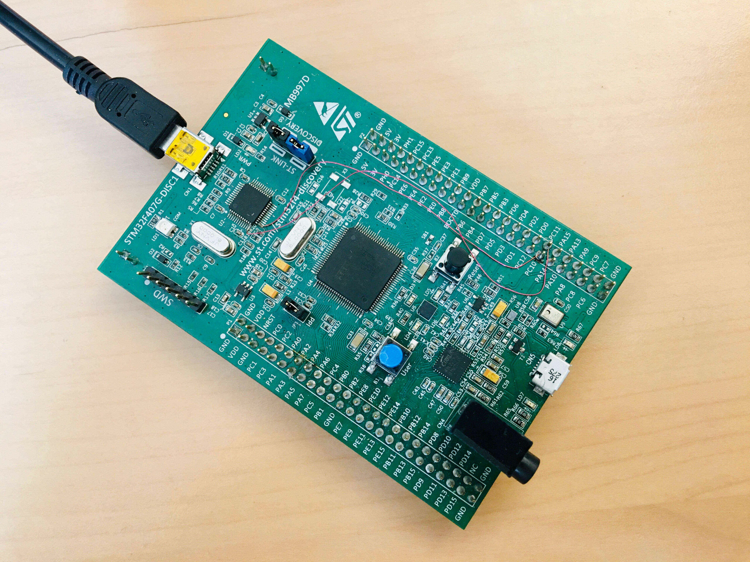
The STM32F407G-Disc1 / MB997D evaluation kit
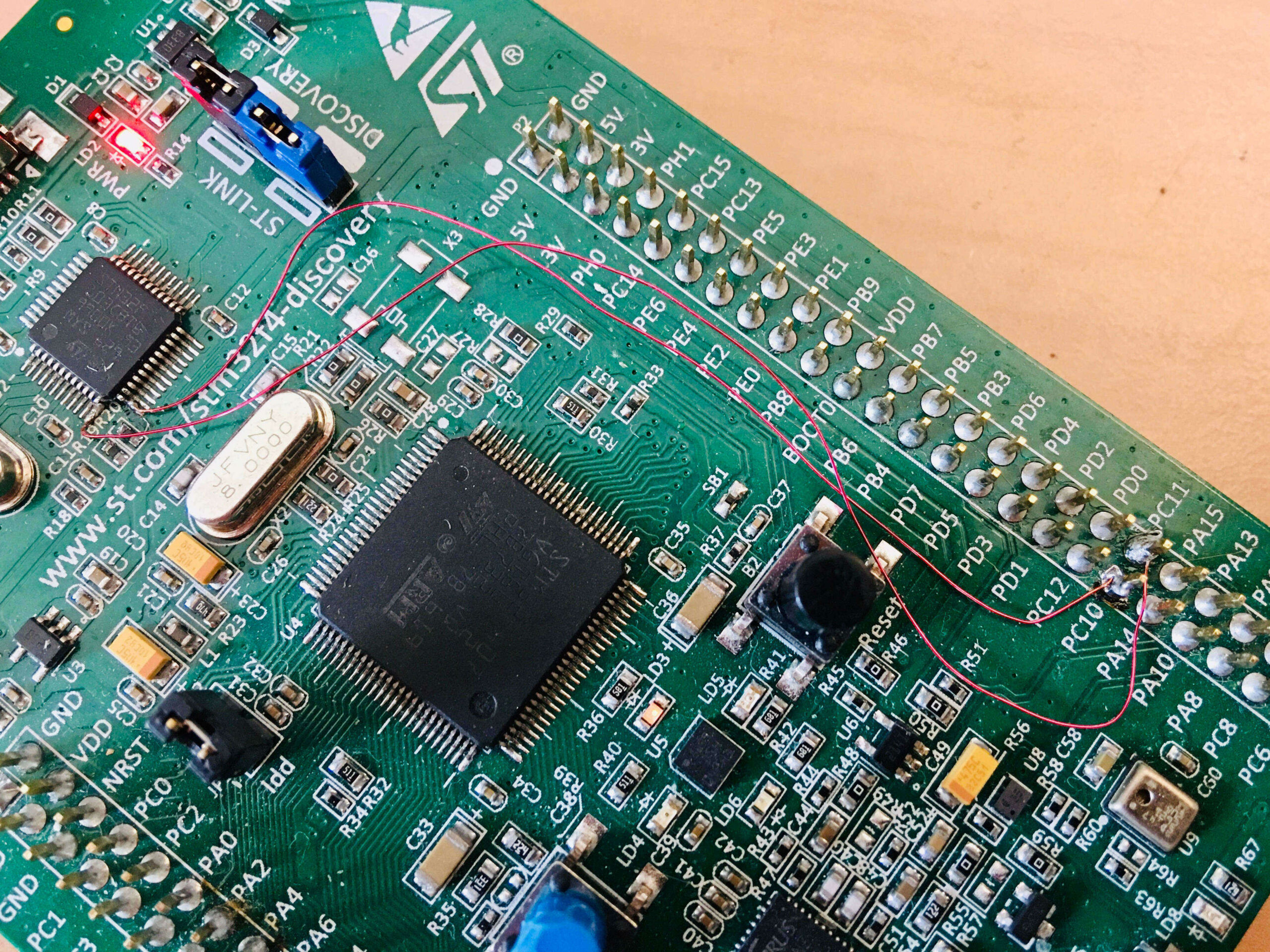
ST-LINK COM port connection to HyperPanelOS ASY1
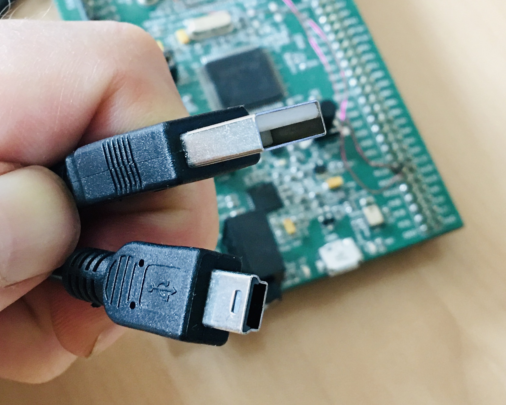
USB cable
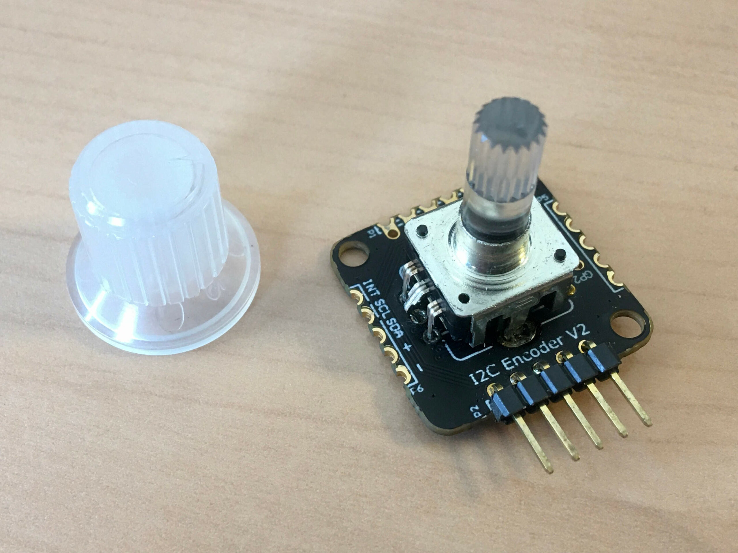
I2C Encoder V2.1 mounted with illuminated RGB encoder
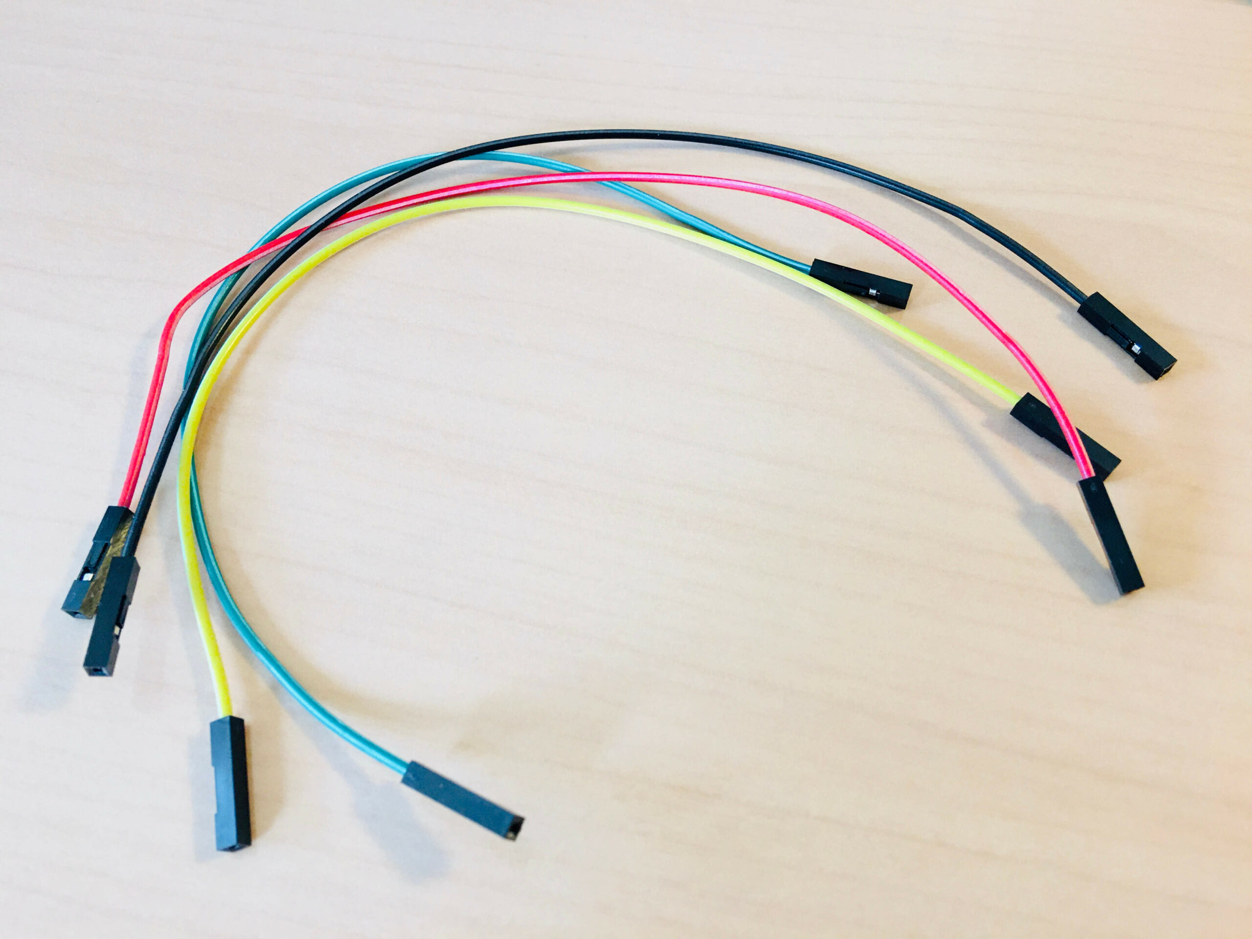
Wires for connections
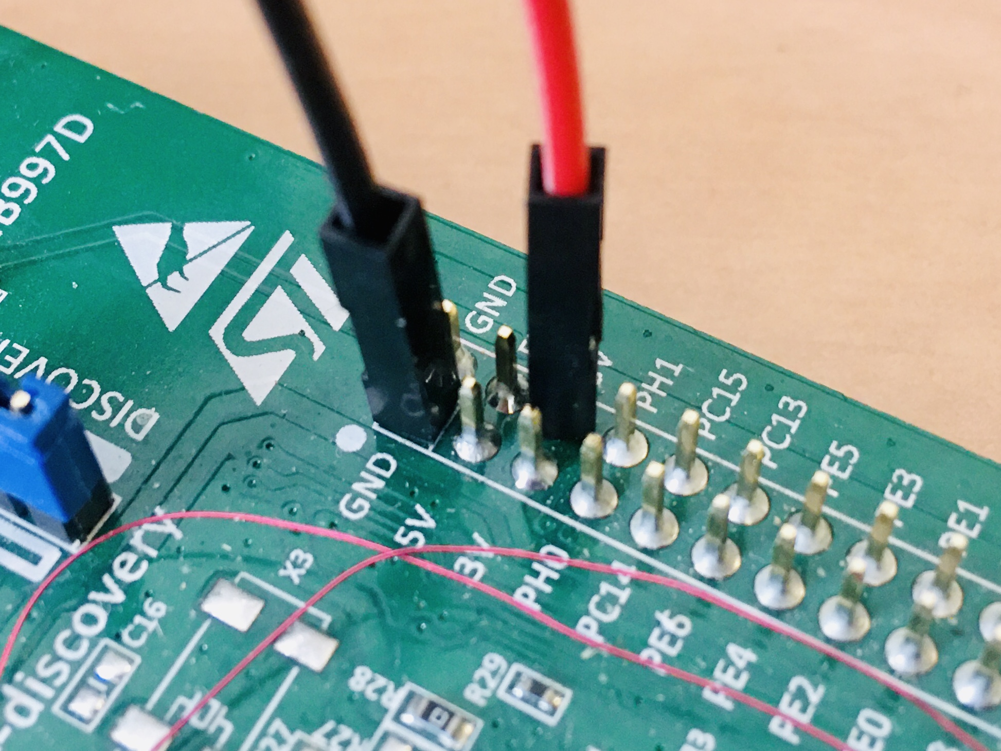
How to connect the power of the encoder to the MB997D
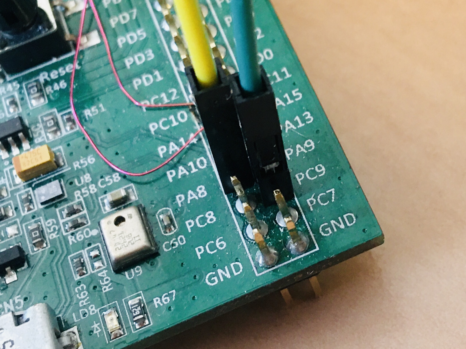
How to connect I2C signals of the encoder to the MB997D
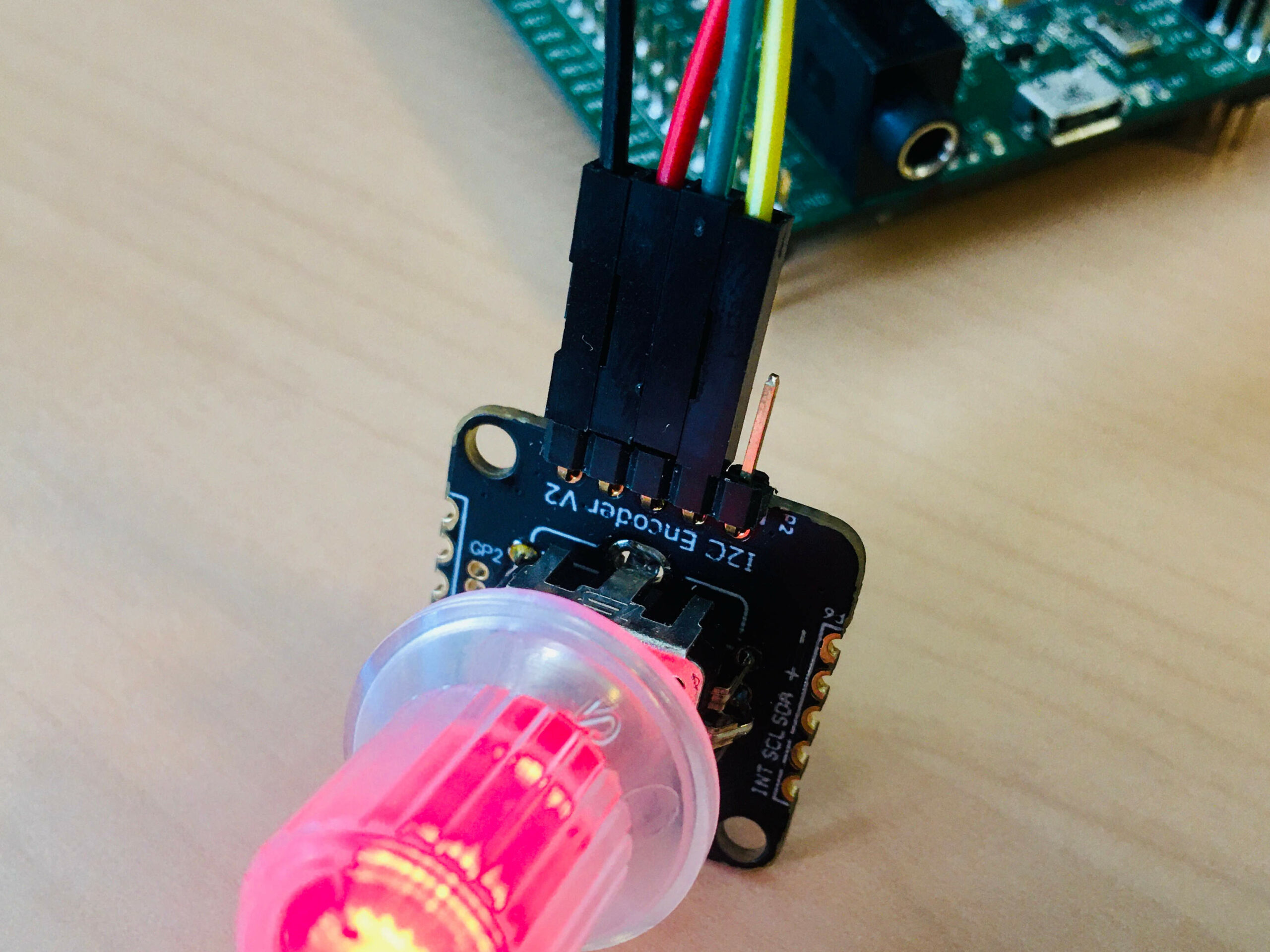
How to connect wires to the encoder
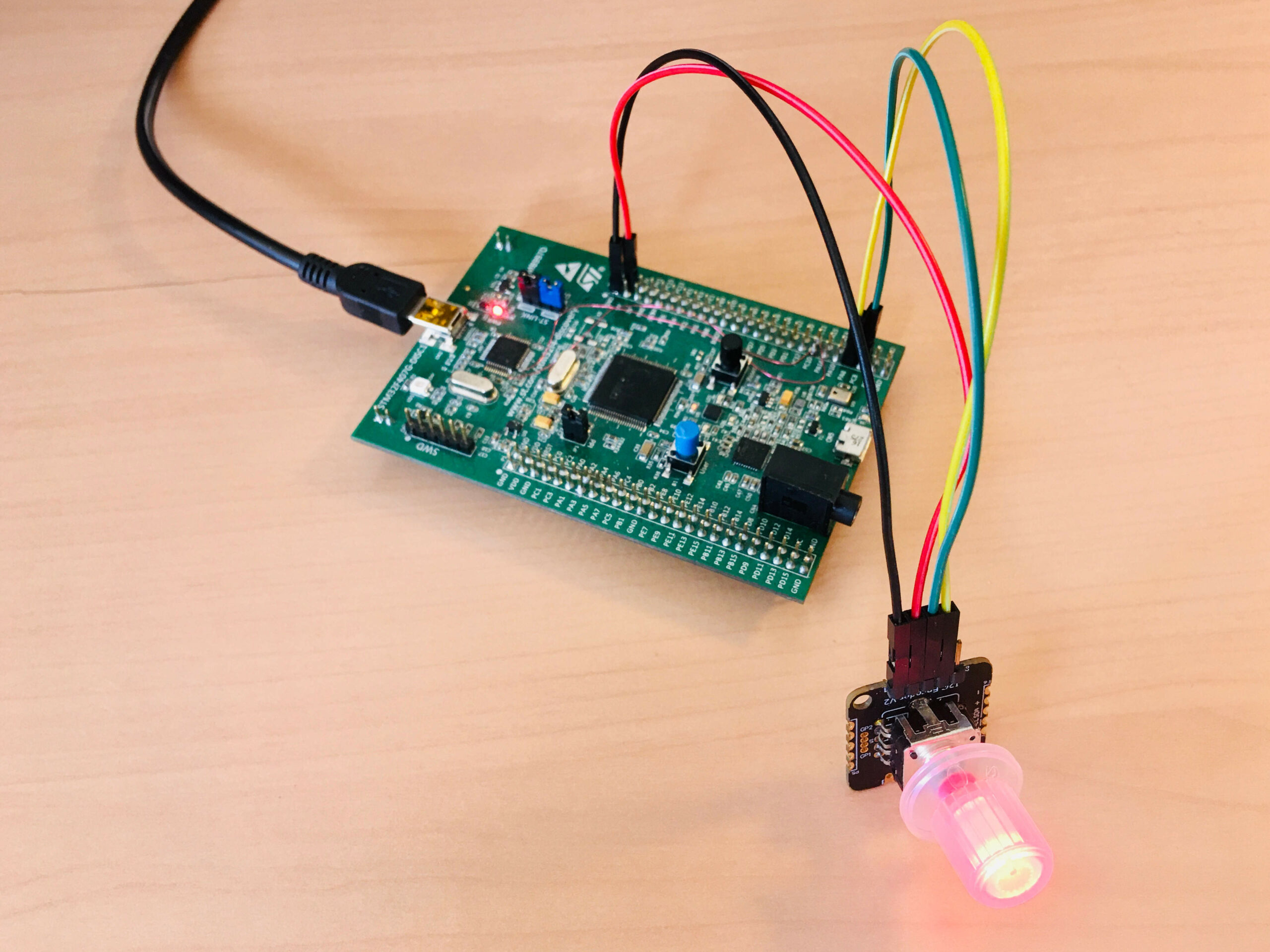
Full assembling
First click, the button is red
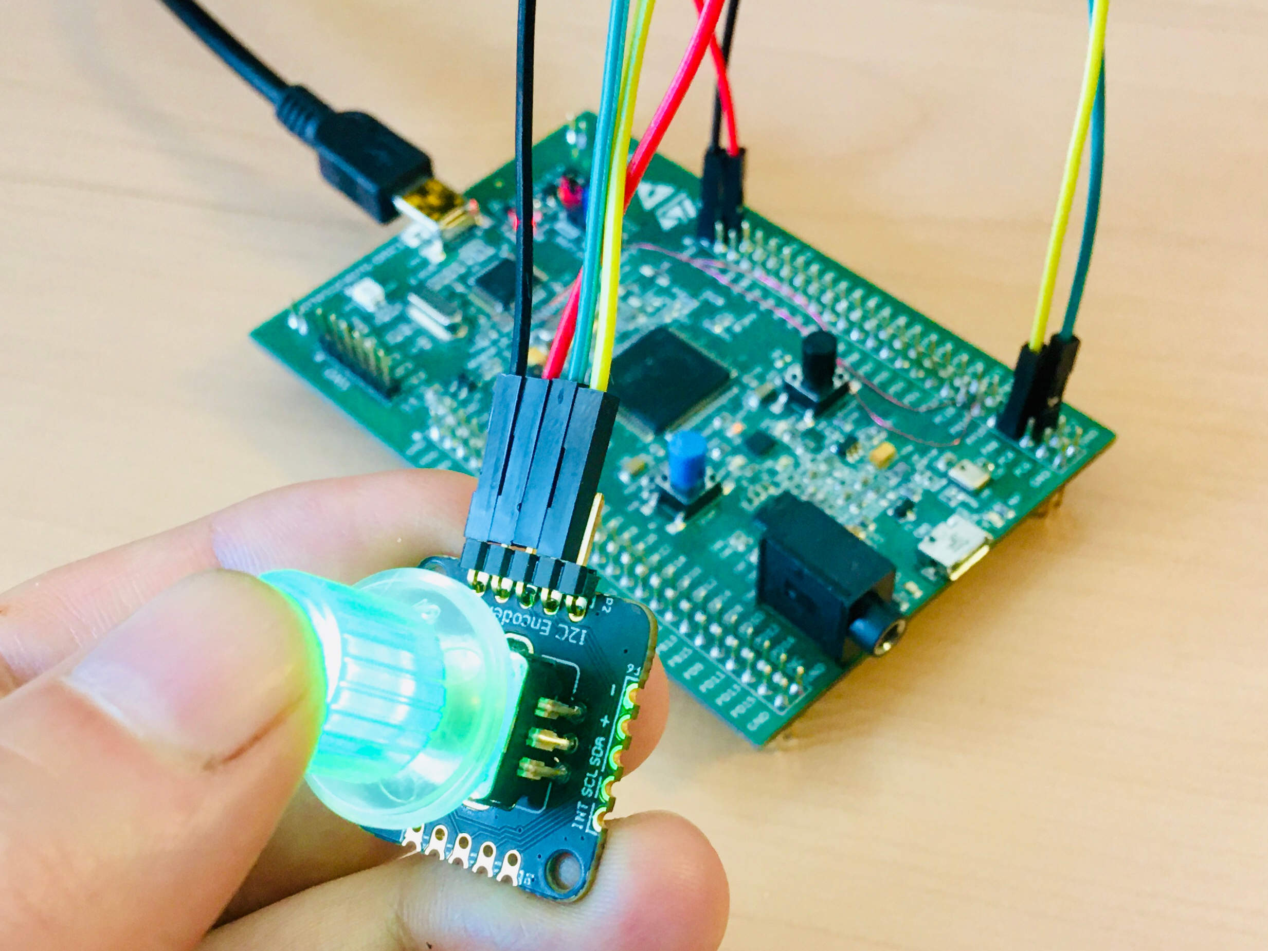
Second click, the button is green
Third click, the button is blue
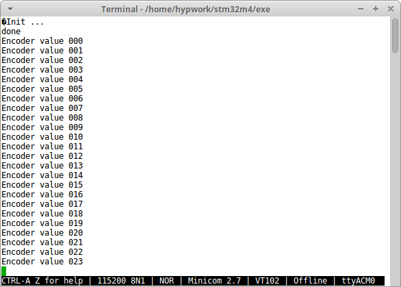
Application messages on serial port
Terminal
 ~/hypv100302/boards/stm32m4/exe >> hgdb
GNU gdb (7.10-1ubuntu3+9) 7.10
Copyright (C) 2015 Free Software Foundation, Inc.
License GPLv3+: GNU GPL version 3 or later <http://gnu.org/licenses/gpl.html>
This is free software: you are free to change and redistribute it.
There is NO WARRANTY, to the extent permitted by law.  Type "show copying"
and "show warranty" for details.
This GDB was configured as "--host=x86_64-linux-gnu --target=arm-none-eabi".
Type "show configuration" for configuration details.
For bug reporting instructions, please see:
<http://www.gnu.org/software/gdb/bugs/>.
Find the GDB manual and other documentation resources online at:
<http://www.gnu.org/software/gdb/documentation/>.
For help, type "help".
Type "apropos word" to search for commands related to "word".

man                    Display again this manual
stm32m4                Send the reset halt command to openocd
armdisconnect          Deconnexion command
peek adr               Read and display  a 32 bit value at adr
poke adr val           Write a val 32 bits value at adr
poke_m adr msk val     Write bits in a 32 bits word with a mask
peekrange base o1 o2   Read 32 bits words from base+o1 to base+o2
affichb adr size       Print a memory area starting at adr
vmio n                 Display the tnote_evt_s debug table
int                    Display the tnote_it debug table
rte                    Return from interrupt
romload stm32m4 app    Write the app executable file in flash
rom stm32m4 app        Connect to target and load app dbg symbols
gpio bank n state      Set GPIO n (0-15) of bank (1-9) to 0/1
clock 0/1/2/3          Output SYSCLK/PLLI2S/HSE/PLL to MO2/PC9
(gdb) romload stm32m4 encoder
Open On-Chip Debugger 0.10.0+dev-00001-g0ecee83-dirty (2017-02-10-06:53)
Licensed under GNU GPL v2
For bug reports, read
    http://openocd.org/doc/doxygen/bugs.html
0x00002ed6 in ?? ()
target halted due to debug-request, current mode: Thread
xPSR: 0x01000000 pc: 0x0000314c msp: 0x10002000
auto erase enabled
target halted due to breakpoint, current mode: Thread
xPSR: 0x61000000 pc: 0x20000046 msp: 0x10002000
wrote 393216 bytes from file encoder.bin in 11.153441s (34.429 KiB/s)
(gdb)